Middle combustion beam for shaft furnace

A technology of burning beam and shaft furnace, applied in the field of kiln equipment, can solve the problems of loss of oil resources, structural rupture, large energy consumption, etc., and achieve the effects of reducing investment and maintenance costs, prolonging service life, and reducing consumption

Inactive Publication Date: 2013-06-05
ZHONGYE-CHANGTIAN INT ENG CO LTD
View PDF5 Cites 0 Cited by
  • Summary
  • Abstract
  • Description
  • Claims
  • Application Information

AI Technical Summary

Problems solved by technology

[0005] 1. The combustion beam is all welded by steel, and only the key parts (such as the top of the oil cooling chamber) are sprayed with a certain thickness of refractory material, and most of its structure is exposed to high temperature environment for a long time. Direct contact with high-temperature materials will cause friction and easily cause its structure to break
At the same time, because it has been impacted by a large number of roasted materials from top to bottom for a long time, dangerous accidents such as beam collapse and broken beams will occur
[0006] 2. Because most of the structure is exposed to high temperature environment for a long time, the temperature in the cooling chamber is extremely high, so water that is prone to scaling at high temperature (that is, the phenomenon of impurities sticking after water evaporates) cannot be used as the cooling medium. oil only
However, the investment and maintenance costs of the oil cooling system 100 are relatively high, and due to frequent oil leakage, it cannot be found and repaired in time, and a large amount of oil resources are lost, resulting in energy waste.
[0007] 3. Limited by the shape of the cavity, when the fuel is sprayed out, most of the heat is concentrated directly below the cavity, which cannot evenly heat the material to be roasted, which will easily cause problems such as low roasting amount and high energy consumption.
At the same time, because the bottom structure of the combustion beam is flat and does not have the function of diversion, the flame at the bottom is relatively concentrated and the combustion area is small

Method used


Image

  • Middle combustion beam for shaft furnace
  • Middle combustion beam for shaft furnace
  • Middle combustion beam for shaft furnace

Examples


Embodiment Construction

[0033] The present invention will be further described in detail below in conjunction with the accompanying drawings and specific embodiments.

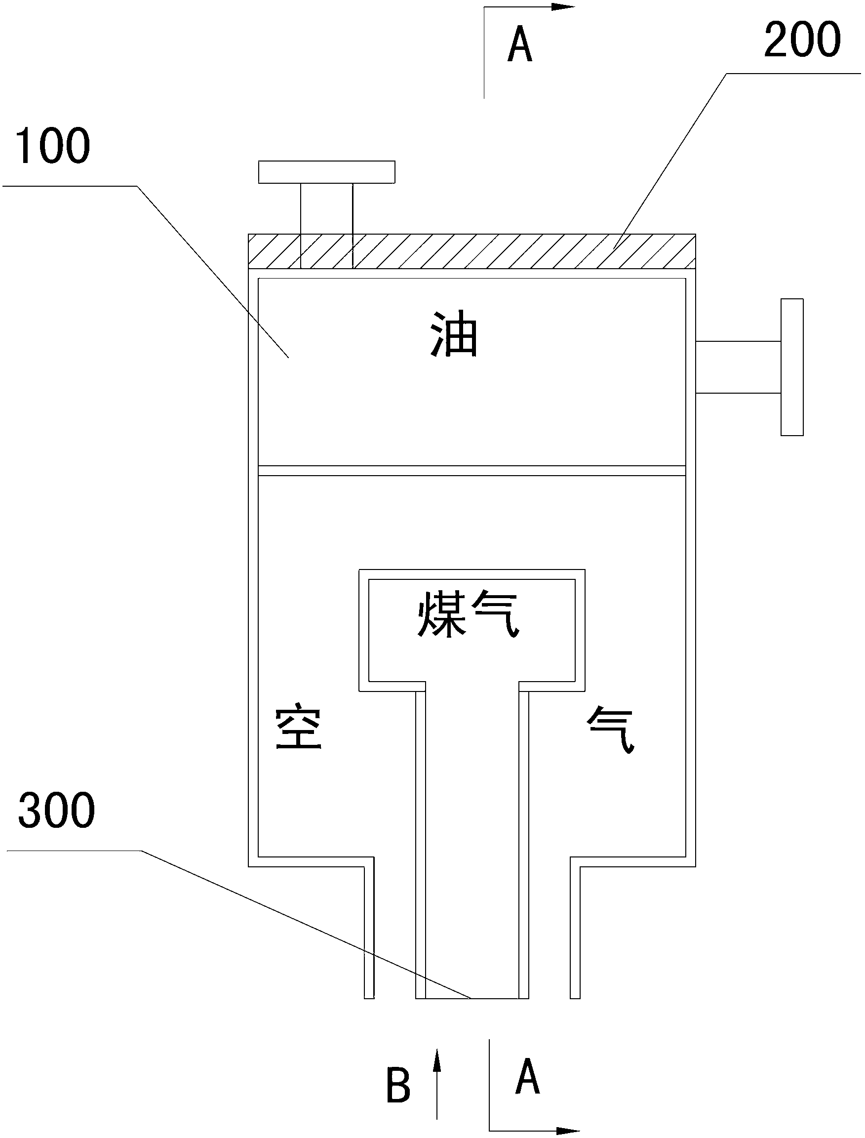
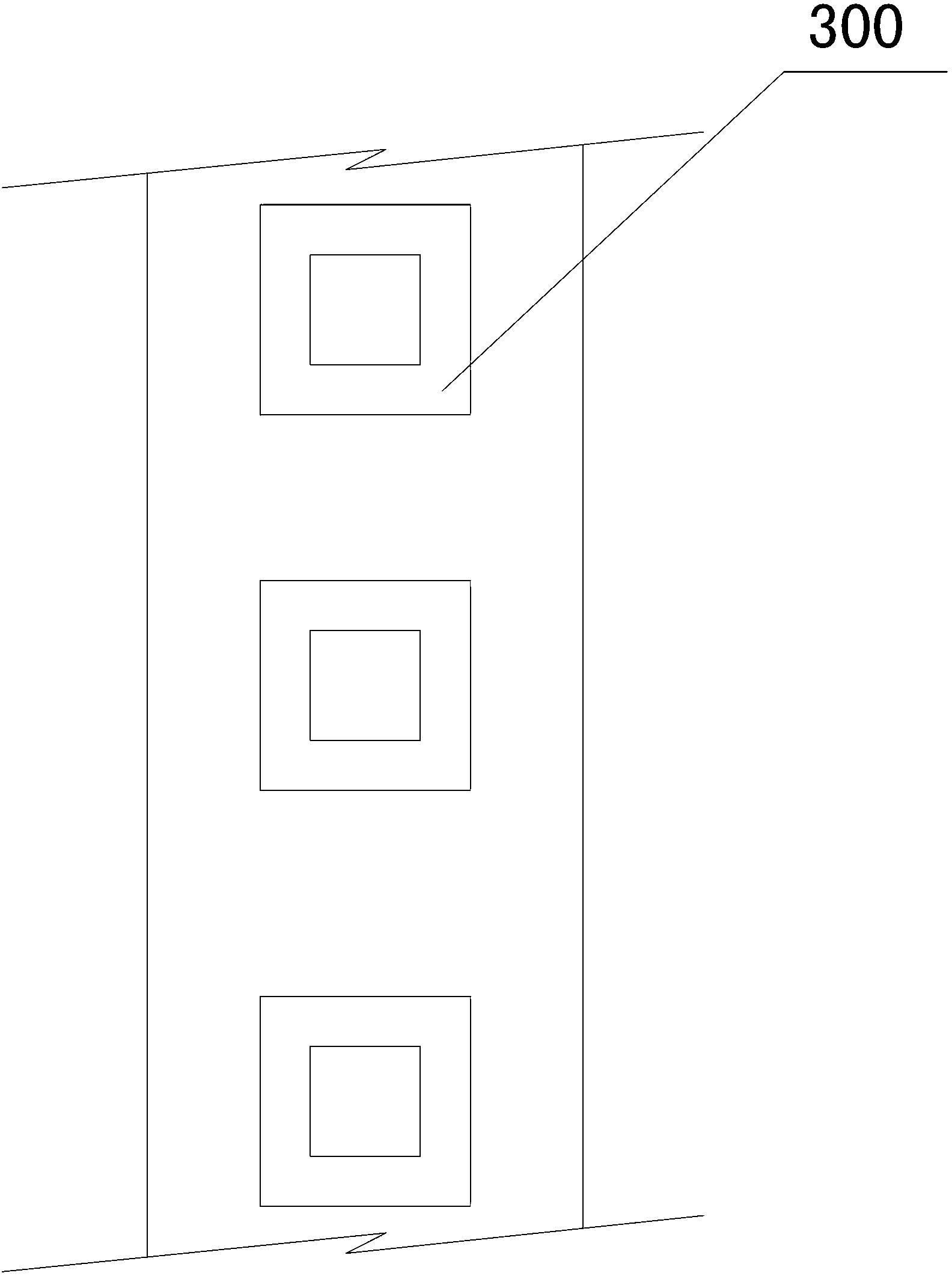
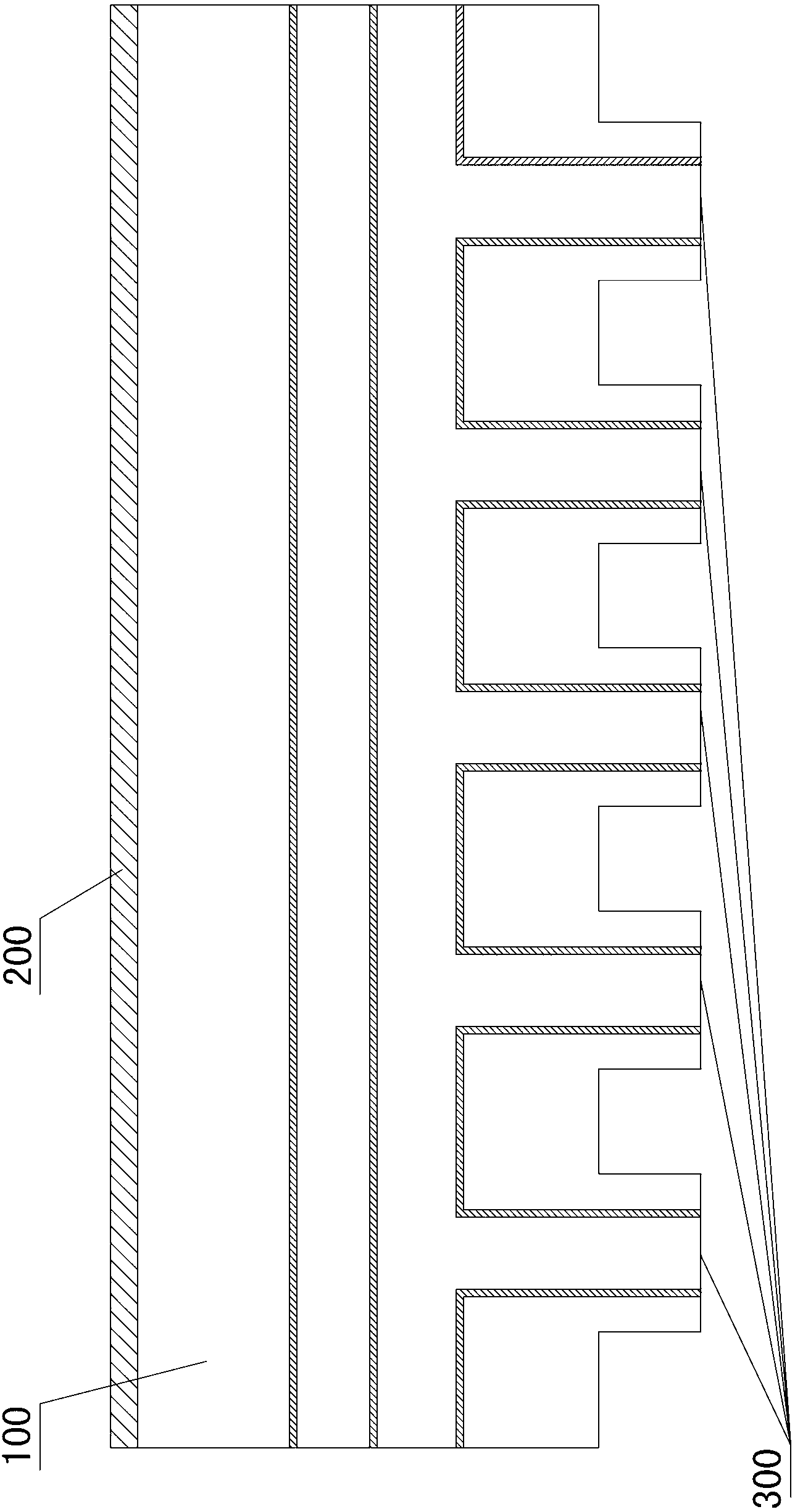
[0034] Such as Figure 4 , Figure 5 and Figure 6 As shown, the present invention is used for the central combustion beam of the shaft furnace, including a cavity 5 and more than one central burner assembly 4 installed in the cavity 5, the bottom of the cavity 5 is provided with a flame ejection port 6, and the cavity 5 is formed by a plurality of water-cooled beams 3 lapped and surrounded. The water-cooled beams 3 are fed with circulating water during operation to reduce the temperature of the middle burner assembly 4 during operation, thereby protecting the middle burner assembly 4 . The water-cooled beam 3 can be made of seamless steel pipe, which has a firm structure, strong load-bearing capacity, is not easy to break, and will not leak. By changing the existing oil-cooled structure into a water-cooled structure, the investmen...


PUM


Abstract

The present invention discloses a middle combustion beam for a shaft furnace. The middle combustion beam comprises a cavity and more than one middle combustion nozzle assemblies arranged inside the cavity, wherein the bottom of the cavity is provided with a flame jet port, and the cavity is formed by overlapping and enclosing a plurality of water cooling beams. The middle combustion beam has advantages of long service life, low operation cost, good operation reliability and the like.

Description

technical field [0001] The invention mainly relates to the field of kiln equipment, in particular to a combustion beam used in a kiln. Background technique [0002] Lime kiln shaft furnace is a natural limestone CaCO 3 Calcination is carried out by the following reaction: CaCO 3 + heat → CaO + CO 2 , a process equipment for generating lime, widely used in steel, building materials and other industries, is an indispensable industrial equipment in such industries; it can also be used for roasting other bulk materials, such as dolomite, etc. The horizontal section of the device is generally circular, semicircular, elliptical, or rectangular. During production, limestone or dolomite raw material is loaded into the shaft furnace from the top, and the raw material passes sequentially from top to bottom through the preheating zone, the calcination zone where the combustion beam with two or three burners is located, the post-combustion zone, cooling zone and finished product exi...

Claims


Application Information

Patent Timeline
Patent Type & Authority Applications(China)
IPC IPC(8): C04B2/12
Inventor 贺新华周浩宇
Owner ZHONGYE-CHANGTIAN INT ENG CO LTD
Why Eureka
Try Eureka