Thermal imager used for surface feature standardization algorithm and three dimensional (3D) laser radar temperature control standardization target

A technology of laser radar and thermal imager, which is applied in the field of calibration devices for measurement, can solve problems such as unfavorable calibration, weak anti-interference ability, and low temperature, and achieve the effects of easy disassembly and transportation, simple and compact structure, and convenient use

Active Publication Date: 2013-06-05
BEIJING INSTITUTE OF TECHNOLOGYGY
View PDF4 Cites 15 Cited by
  • Summary
  • Abstract
  • Description
  • Claims
  • Application Information

AI Technical Summary

Problems solved by technology

Its disadvantages are: in an environment with serious infrared interference, such as an outdoor environment under sunlight, it is difficult to be identified because it cannot generate heat, so it is not suitable for outdoor calibration operations
Its disadvantages are: the hand-held calibration board pressed by several layers of boards generally has a relatively low temperature and weak anti-interference ability; due to the diffraction effect of the hole, the accuracy is affected to a certain extent; The calibration of lidar provides enough coplanar points
Its disadvantages are: due to the distance from the heat source and the transmission direction of infrared rays, the brightness of each floor space is different, which is not conducive to calibration; the temperature control function is not realized; the infrared light intensity is low, which is not conducive to outdoor calibration
Since the visible light camera mainly receives visible light, it can be calibrated under visible conditions; while the thermal imager mainly receives infrared light and is not sensitive to visible light, so the conventional calibration target that does not emit infrared light is not suitable for "thermal imager— Calibration of the "LiDAR" system

Method used


Image

  • Thermal imager used for surface feature standardization algorithm and three dimensional (3D) laser radar temperature control standardization target
  • Thermal imager used for surface feature standardization algorithm and three dimensional (3D) laser radar temperature control standardization target

Examples


Embodiment Construction

[0023] The present invention will be described in detail below with reference to the accompanying drawings and examples.

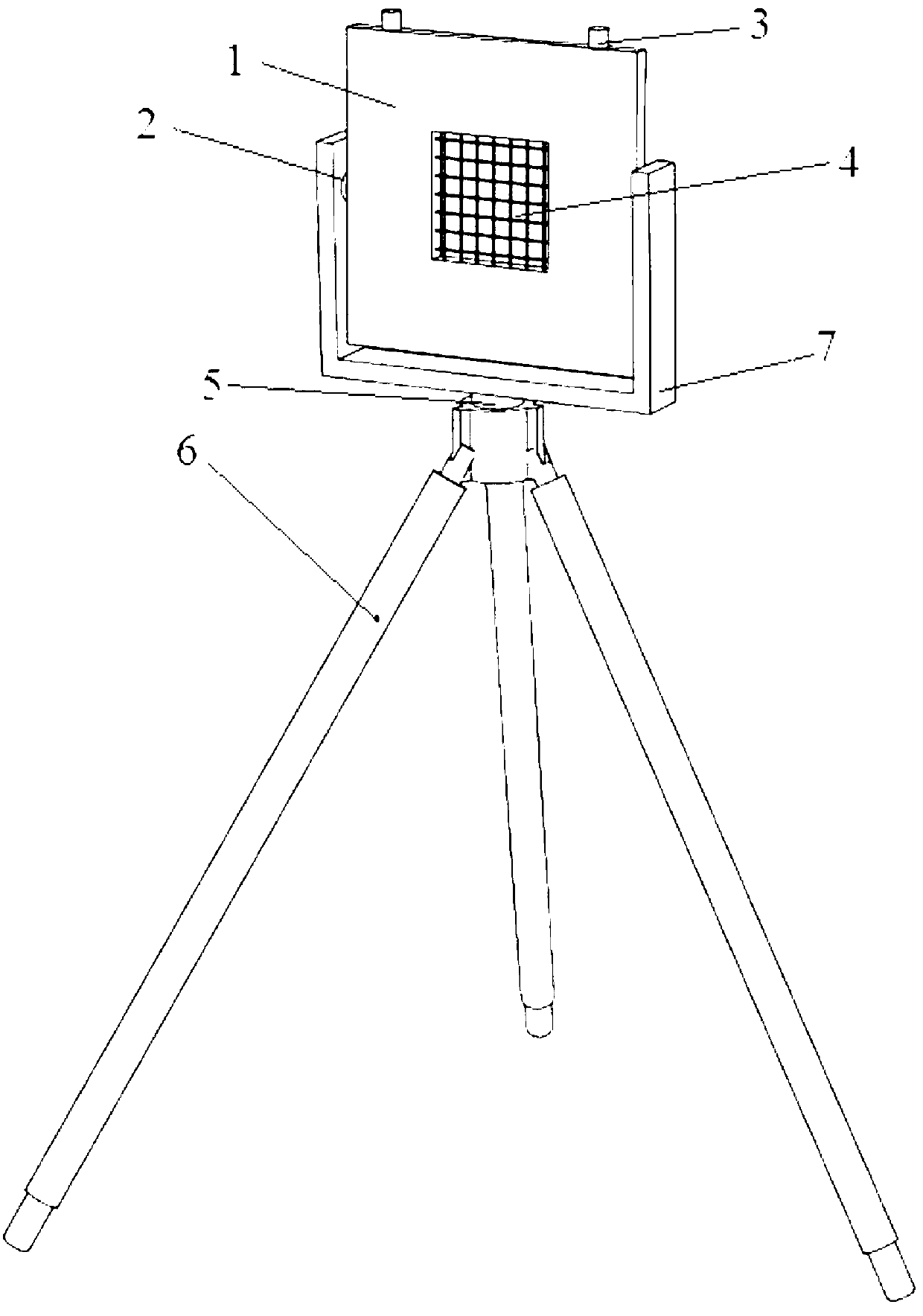
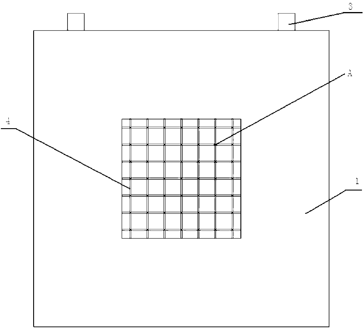
[0024] Such as figure 1 As shown, this embodiment provides a thermal imager and a 3D lidar temperature-controlled calibration target for surface feature calibration algorithms, including a heating net 4, a calibration plane 1, a heat-insulating handle 3, a support frame 7, a pitch shaft 2, Horizontal rotating shaft 5, tripod 6, temperature controller, temperature sensor and power cord.

[0025] Among them, the calibration plane 1 is made of heat-resistant hard material, and the calibration plane 1 is used to provide coplanar laser point cloud data for 3D lidar. There is a square hole in the middle of the calibration plane 1, and the heating net 4 is a grid formed by winding a complete heating wire with a high-temperature insulating layer on the outside in the square hole of the calibration plane 1. The plane where the heating net 4 is located should be en...


PUM


Abstract

The invention relates to a thermal imager used for surface feature standardization algorithm and a three dimensional (3D) laser radar temperature control standardization target. The standardization target comprises a standardization plane, a heating net, a support frame, a temperature controlling device, a temperature sensor, a tripod, a heating separating handle, a pitching revolving shaft, a horizontal revolving shaft and a power line. The horizontal revolving shaft and the pitching revolving shaft are used for adjusting the posture of the standardization target. The tripod is used for adjusting the height of the standardization target. Heating power of the heating net is adjusted by the temperature controlling device by the fact that the electric current flows through the heating net is controlled by the temperature controlling device, thus the temperature of the heating net is adjusted. An infrared feature angle point is provided for the thermal imager on the cross position of the heating net. The standardization surface feature value in a thermal imager coordinate system is obtained by using the infrared feature angle point on the thermal imager collection standardization target. Coplanar point cloud data are provided for the 3D laser radar by the standardization plane, thus the surface feature of the standardization plane in the laser radar coordinate system can be obtained. The standardization of the thermal imager and the 3D laser radar is completed through the standardization algorithm based on the surface feature at last.

Description

technical field [0001] The invention relates to a calibration device for measurement, in particular to a thermal imager and a 3D laser radar temperature-controlled calibration target for a surface feature calibration algorithm. Background technique [0002] The spatial calibration of 3D lidar and thermal imager is the basis for constructing a spatial combined perception system under low-light conditions. The calibration algorithm of the "thermal imager-lidar" system is generally consistent with the calibration algorithm of the "visible light camera-lidar" system, which can be divided into three main types: calibration based on plane features, calibration based on contour features, and calibration based on Calibration of feature points. At present, scholars at home and abroad have made a lot of achievements in the design of the above three algorithms. [0003] Due to the lack of structured objects with precise size characteristics in the natural environment, it is difficult...

Claims


Application Information

Patent Timeline
Patent Type & Authority Applications(China)
IPC IPC(8): G01J5/00G01S7/497
Inventor 付梦印宗民杨毅朱昊王美玲
Owner BEIJING INSTITUTE OF TECHNOLOGYGY
Why Eureka
Try Eureka