Standard logic process-compatible difference framework NVM (Non-Volatile Memory) unit

A memory cell and logic technology, applied in the field of differential architecture NVM memory cells, to achieve the effects of improving stability, reducing the influence of offset, and improving stability

Inactive Publication Date: 2013-06-05
SUZHOU KUANWEN ELECTRONICS SCI & TECH
View PDF14 Cites 7 Cited by
  • Summary
  • Abstract
  • Description
  • Claims
  • Application Information

AI Technical Summary

Problems solved by technology

However, these structures are affected by transistor size and parasitic effects, and the cost and reliability limitations brought about by them are the key to restricting the development of NVM with this structure, and it is unavoidable

Method used


Image

  • Standard logic process-compatible difference framework NVM (Non-Volatile Memory) unit
  • Standard logic process-compatible difference framework NVM (Non-Volatile Memory) unit
  • Standard logic process-compatible difference framework NVM (Non-Volatile Memory) unit

Examples


Embodiment 1

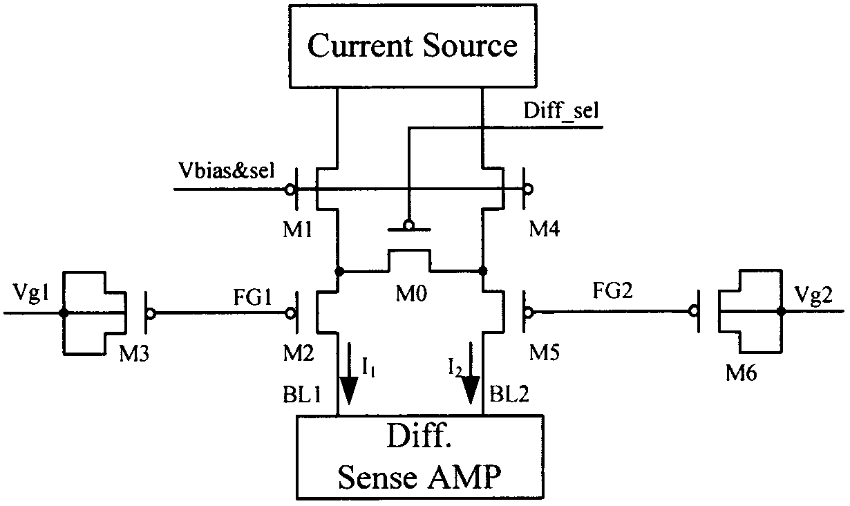
[0030] see figure 1 As shown, the uppermost module is a constant current source, which is usually implemented by a MOS current source operating in the saturation region. Its advantage is that it is compatible with standard processes and the current is stable. MOS transistor M1 and MOS transistor M4 are selection transistors, the gate of which is connected to the gate voltage Vbias&sel of the word line, the source is connected to the above-mentioned constant current source module, the drain is respectively connected to MOS transistor M2 and MOS transistor M5, and the substrate is directly connected to the source Usually, the gating voltage is high voltage, so there are special requirements for the size of the tube and the thickness of the gate oxide, and the two gating tubes also bear a certain bias effect.

[0031] MOS transistor M2 and MOS transistor M5 are programming transistors, their gates are respectively connected to the gates of MOS transistor M3 and MOS transistor M6 ...

Embodiment 2

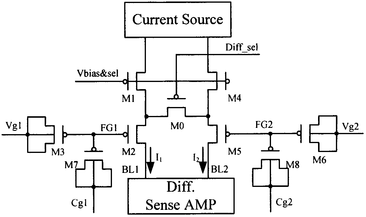
[0034] see figure 2 shown in figure 1 on the basis of figure 2 Two more identical small capacitance MOS transistors M7 and MOS transistor M8 are added to the floating gate, and the nodes Vg1 and Cg2 are connected, and Vg2 and Cg1 are connected, so that cross-coupling is realized, which can improve the reading stability more effectively sex. The change of its connection method is that there are two more MOS transistors M7 and MOS transistor M8, and the connection method of MOS transistor M7 and MOS transistor M3 is exactly the same, and the gate is shared with the MOS transistor M2, and then the source and drain substrates are all connected. Its role is relative to capacitance. The connection method of MOS tube M8 is exactly the same as that of MOS tube M7.

Embodiment 3

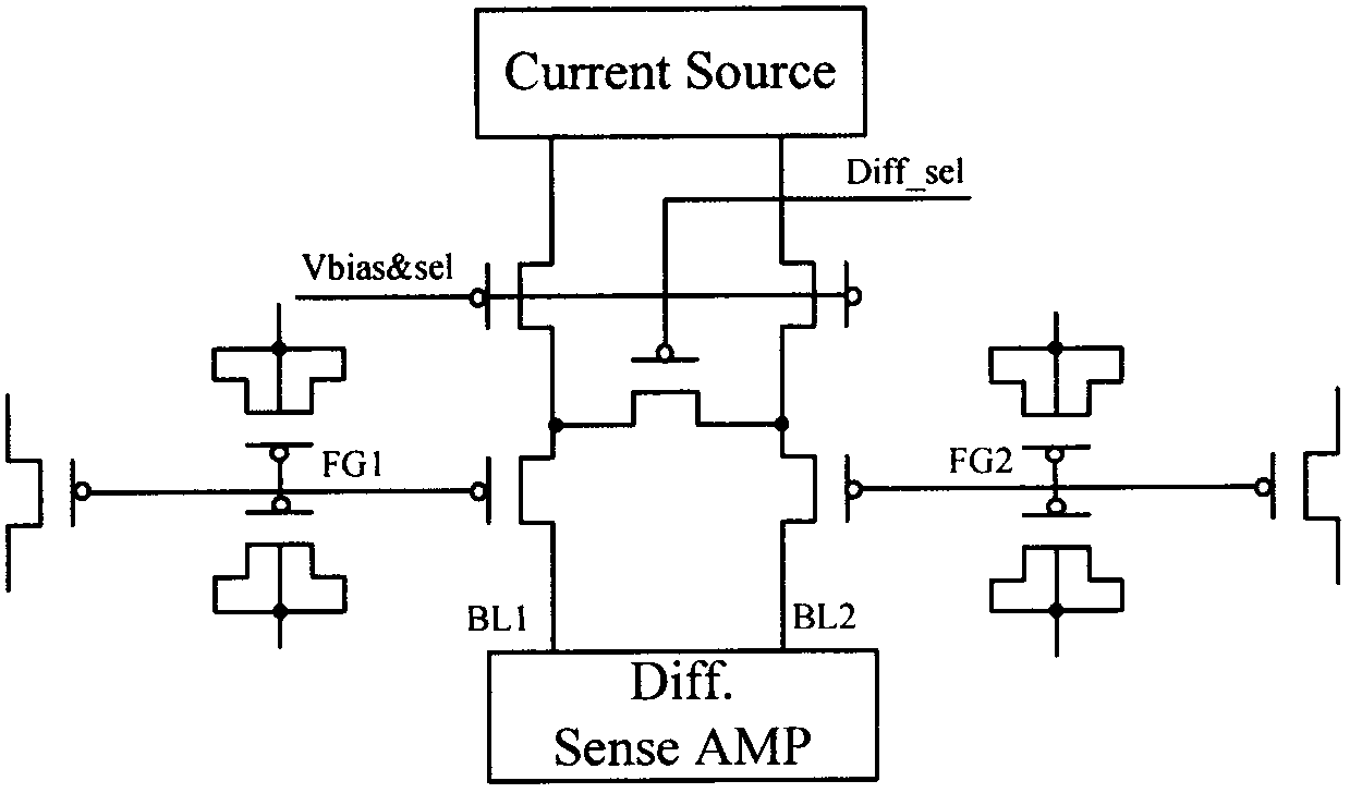
[0036] see image 3 shown in figure 2 on the basis of image 3 Two more identical MOS transistors are added on the floating gate. The connection and function of these two transistors are the same as those of MOS transistor M2 and MOS transistor M5, but they are only responsible for writing operations, that is, separate read and write methods are used here. The advantage of this is that it can not only retain various advantages of the read circuit of the differential structure, but also maintain the fast and effective writing effect.


PUM


Abstract

The invention discloses a standard logic process-compatible difference framework NVM (Non-Volatile Memory) unit which comprises two single NVM units, and a biased power supply and an input / output circuit which are connected with the two single NVM units, each single NVM unit has a floating gate framework and comprises a selective transistor and a programming transistor which serve as gating and biasing actions on the floating gate, as well as a control transistor for sharing together with a grid electrode of the programming transistor through adopting a capacitor connection method. By adopting the difference framework, the sizes of the transistors can be reduced, the number of the transistors on the surface can be doubled, the requirement on the transistor can be integrally lowered, the area change of the memory units can not be large, the working voltage can be reduced, the power consumption can be reduced necessarily through the reduction of the working voltage, the stability can be obviously improved, so that the standard logic process-compatible difference framework NVM unit has important research significance and wide market prospects.

Description

technical field [0001] The invention relates to a differential architecture NVM memory unit, in particular to a differential architecture NVM memory unit compatible with standard logic technology. Background technique [0002] We generally divide memory into two categories: one is volatile, that is, the memory loses the information stored in it immediately after the system is turned off, and it needs a continuous power supply to maintain data; the other is non-volatile, which Data information can still be retained when the system is turned off or in a state of no power. Most memory is non-volatile memory. [0003] A traditional non-volatile memory is a MOS transistor, which has a gate, a source and a drain. Different from other MOS transistors, his gate consists of two parts: floating gate and control gate. The floating gate is between the gate oxide layer and the pole oxide layer, and the pole oxide layer is used to isolate the floating gate. Between the control gate an...

Claims


Application Information

Patent Timeline
Patent Type & Authority Applications(China)
IPC IPC(8): G11C16/06
Inventor 李力南翁宇飞王子欧
Owner SUZHOU KUANWEN ELECTRONICS SCI & TECH
Why Eureka
Try Eureka