
A Design Method of High Power and High Beam Quality Laser

A design method and high-beam technology, applied in the laser field, can solve the problems of reducing the quality of the laser beam and increasing the difficulty of laser alignment, and achieve the effect of improving the quality of the beam, increasing the power, and increasing the degree of collimation

Inactive Publication Date: 2016-04-13
XIDIAN UNIV
View PDF3 Cites 0 Cited by
  • Summary
  • Abstract
  • Description
  • Claims
  • Application Information

AI Technical Summary

Problems solved by technology

[0002] When the laser oscillates in the resonator, high-order modes and low-order modes will be generated. Especially in high-power pumping, the high-order modes are easy to vibrate, and the generation of high-order modes reduces the beam quality of the laser and makes it difficult to align the laser.

Method used


Image

  • A Design Method of High Power and High Beam Quality Laser
  • A Design Method of High Power and High Beam Quality Laser
  • A Design Method of High Power and High Beam Quality Laser

Examples


Embodiment 1

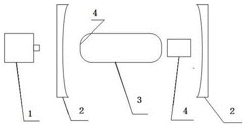
[0016] Such as figure 1 As shown, the optical resonant cavity 2 is two mirrors parallel to each other, with a heat sink outside, and the optical resonant cavity 2 has a Nd:YAG medium 3 and an acousto-optic Q-switching switch 5 . The shape of the Nd:YAG medium 3 is a convex flat-top shape, and the temperature of the Nd:YAG medium is cooled by a fan.

[0017] The end pump 1 is on the end face of the optical resonant cavity 2, and the end pump 1 irradiates the receiving surface 4 of the Nd:YAG medium, and the symmetry plane between the receiving surface 4 and the receiving surface of the Nd:YAG medium is a plane with an inscribed circle radius of 1 cm. In this case, the transmittance of the medium to the light source is 20%.

[0018] Under the action of the convex flat-top medium, the pump light source will form a convergence, and the number of inverted particles in the medium in the resonant cavity will be significantly increased. Under the action of the acousto-optic Q-switchi...

Embodiment 2

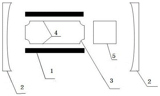
[0020] Such as figure 2 As shown, there is a concave flat-top Nd:YAG medium 4 and an acousto-optic Q-switching switch 5 between the two parallel mirrors of the optical resonant cavity 2. There is a heat sink outside the optical resonant cavity 2, and the fan cools the concave flat-top medium .

[0021] The pumping light source 1 is side pumping, and the side pumping is on the side of the optical resonant cavity 2, the receiving surface 4 of the Nd:YAG medium is a plane, and its inscribed circle radius is 1cm, and the transparent surface of the concave flat-top Nd:YAG medium 20% failure rate

[0022] The side pump increases the number of reversed particles in the medium in the resonant cavity. Under the action of the acousto-optic Q-switched switch, the number of reversed particles is continuously accumulated. When the Q switch is turned on, the oscillating light is stimulated to emit Amplification and power increase form a pulsed laser. Due to the unique shape of the medium...

Embodiment 3

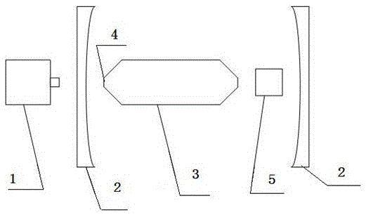
[0024] Such as image 3 As shown, the structure of this embodiment is basically the same as that of Embodiment 1. The difference is that the shape of the Nd:YAG medium 3 is a conical flat-top shape, and the conical flat-top Nd:YAG medium is in effect the same as the convex flat top. The shape medium is the same, the radius of the inscribed circle of their receiving surface is 1cm, and the same effect can be obtained.

[0025] The shape of the Nd:YAG medium 3 can also be a flat top shape of a spherical surface, a flat top shape of an ellipsoidal surface, a flat top shape of a parabolic surface, and a flat top shape of a hyperbolic surface. Their functions and effects are also the same, and will not be detailed here. introduce.


PUM


Abstract

The invention relates to a design method for a high-power high-beam-quality laser. The design method for the high-power high-beam-quality laser includes a pump light source, an optical resonant cavity, an acousto-optic Q-switch, heat sinks, a fan and an Nd: YAG (yttrium aluminium garnet crystal) medium, wherein heat sinks are arranged on the outside of the two parallel mirrors of the optical resonant cavity, and light beams of the pump light source illuminate the receiving surface of the Nd: YAG medium. The design method for the high-power high-beam-quality laser is characterized in that the Nd: YAG medium and the acousto-optic Q-switch are arranged inside the optical resonant cavity, the Nd: YAG medium is in a convex surface flat top shape or a concave surface flat top shape, the receiving surface of the Nd: YAG medium and the plane of symmetry of the receiving surface are planes with an incircle radius no less than 1cm, and the fan cools the Nd: YAG medium. According to the design method for the high-power high-beam-quality laser, the laser changes the appearance of the Nd: YAG medium, restrains the high-order mode produced in an oscillating process, improves the beam quality, increases the degree of laser alignment, and meanwhile increases power by adding an acousto-optic Q-switch.

Description

technical field [0001] The invention belongs to the technical field of lasers, and relates to a diode-pumped solid-state laser device, in particular to a design method of a high-power high-beam quality laser. Background technique [0002] When the laser oscillates in the resonator, high-order modes and low-order modes will be generated. Especially in high-power pumping, the high-order modes are easy to vibrate, and the generation of high-order modes reduces the beam quality of the laser and makes it difficult to align the laser. So how to suppress the generation of high-order modes is the primary problem to solve the laser beam quality. [0003] When the laser is oscillating, the high-order mode is easily affected by the shape of the medium and thus suppressed, while the low-order mode can be easily oscillated, which improves the beam quality. Contents of the invention [0004] The purpose of the present invention is to provide a design method for a laser with high power ...

Claims


Application Information

Patent Timeline
Patent Type & Authority Patents(China)
IPC IPC(8): H01S3/06H01S3/11
Inventor 屈鹏飞王石语过振蔡德芳李兵斌
Owner XIDIAN UNIV
Learn More