Electromagnetic shielding method and products thereof

A technology of electromagnetic shielding and products, applied in the fields of magnetic/electric field shielding, chemical instruments and methods, electrical components, etc., can solve the problems of poor shielding performance and zero electromagnetic shielding performance

Inactive Publication Date: 2013-06-05
SHENZHEN FUTAIHONG PRECISION IND CO LTD
View PDF0 Cites 9 Cited by
  • Summary
  • Abstract
  • Description
  • Claims
  • Application Information

AI Technical Summary

Problems solved by technology

However, since copper and stainless steel are only conductive but not magnetic, the plastic substrate treated by the above method has poor shielding performance in the magnetic field, especially for the electromagnetic shielding of industrial frequency (that is, the frequency of AC power used in industry, 50Hz). almost zero performance

Method used


Image

  • Electromagnetic shielding method and products thereof
  • Electromagnetic shielding method and products thereof

Examples


Embodiment 1

[0030] Sand blasting treatment: the sand used is ceramic sand of model 80#, and the sand blasting pressure is 1.2MPa.

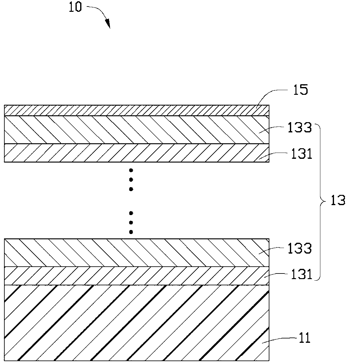
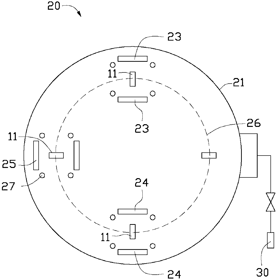
[0031] Sputtering metal composite layer 13: vacuumize coating chamber 21 to 4.0×10 -3 Pa, then pass into the argon gas of flow rate about 180sccm in the coating chamber 21, the power that the first target material 23 is set is 10kW, the power that the second target material 24 is set is 5kW; Described film coating temperature is room temperature, and film coating time is 6min. Wherein, the first target material 23 is a copper layer, and the second target material 24 is a nickel layer. The thickness of the metal composite layer 13 is 0.2 μm.

[0032] Sputtering protective layer 15: set its power to 8kw; argon gas flow rate to 180 sccm; the temperature of the coating chamber 21 is room temperature, and the coating time can be 5 minutes. Wherein, the third target material 25 is a stainless steel layer. The thickness of the protection layer 15 is 0.1 μm.

Embodiment 2

[0034] Sand blasting treatment: the sand used is ceramic sand of model 80#, and the sand blasting pressure is 1MPa.

[0035] Sputtering metal composite layer 13: vacuumize coating chamber 21 to 6.0×10 -3 Pa, then pass into the argon gas that flow rate is about 200sccm in coating chamber 21, the power that the first target material 23 is set is 12kW, the power that the second target material 24 is set is 6kW; Described coating temperature is room temperature, coating time is 10min. Wherein, the first target material 23 is a silver layer, and the second target material 24 is a nickel layer. The thickness of the metal composite layer 13 is 0.4 μm.

[0036] Sputtering protective layer 15: set its power to 10kw; argon gas flow rate to 200 sccm; the temperature of the coating chamber 21 is room temperature, and the coating time can be 10 minutes. Wherein, the third target material 25 is a stainless steel layer. The thickness of the protection layer 15 is 0.3 μm.


PUM

PropertyMeasurementUnit
thicknessaaaaaaaaaa
thicknessaaaaaaaaaa
thicknessaaaaaaaaaa

Abstract

The invention provides an electromagnetic shielding method. The electromagnetic shielding method comprises the following steps: providing a plastic substrate, and using a vacuum coating method to form a metal composite layer on the plastic substrate, wherein the metal composite layer is formed by alternating deposit of a plurality of first metal layers and a plurality of second metal layers, the first metal layers are copper layers or silver layers or lithium layers, and the second metal layers are nickel layers. The invention further provides products manufactured by using the electromagnetic shielding method.

Description

technical field [0001] The invention relates to an electromagnetic shielding method and a product. Background technique [0002] In the prior art, vacuum coating, electroless plating, or a combination of electroless plating and electroplating are usually used to sequentially form a copper layer and a stainless steel protective layer on the plastic substrate, so that the plastic substrate has electromagnetic shielding properties after metallization. However, since copper and stainless steel are only conductive but not magnetic, the plastic substrate treated by the above method has poor shielding performance in the magnetic field, especially for the electromagnetic shielding of industrial frequency (that is, the frequency of AC power used in industry, 50Hz). Performance is next to zero. Contents of the invention [0003] In view of this, the present invention provides an electromagnetic shielding method that can solve the above problems. [0004] In addition, the present i...

Claims


Application Information

Patent Timeline
Patent Type & Authority Applications(China)
IPC IPC(8): H05K9/00B32B15/08C23C14/20C23C14/16C23C14/35
CPCB32B15/08C23C14/35H05K9/0084H05K9/0088C23C14/20H05K9/00C23C14/16C23C14/205C23C14/352C23C28/023Y10T428/12556
Inventor 曹达华
Owner SHENZHEN FUTAIHONG PRECISION IND CO LTD
Why Eureka
Try Eureka