Check patentability & draft patents in minutes with Patsnap Eureka AI!

Efficient blood oxygen saturation detection circuit

A detection circuit and saturation technology, applied in the electronic field, can solve the problems of low blood oxygen saturation accuracy, increased measurement cost, limited range, etc., and achieve the effects of high sensitivity, simple circuit, and easy integration

Inactive Publication Date: 2013-06-12
TIANJIN UNIV
View PDF7 Cites 4 Cited by
  • Summary
  • Abstract
  • Description
  • Claims
  • Application Information

AI Technical Summary

Problems solved by technology

[0004] In the process of the above operation, there are strict requirements on device parameters and measurement conditions. When the calculation is complicated and takes up a large number of CPU machines, the measurement cost is increased, the scope of practical application is limited, and the obtained blood oxygen saturation accuracy not tall

Method used


Image

  • Efficient blood oxygen saturation detection circuit
  • Efficient blood oxygen saturation detection circuit
  • Efficient blood oxygen saturation detection circuit

Examples


Embodiment 1

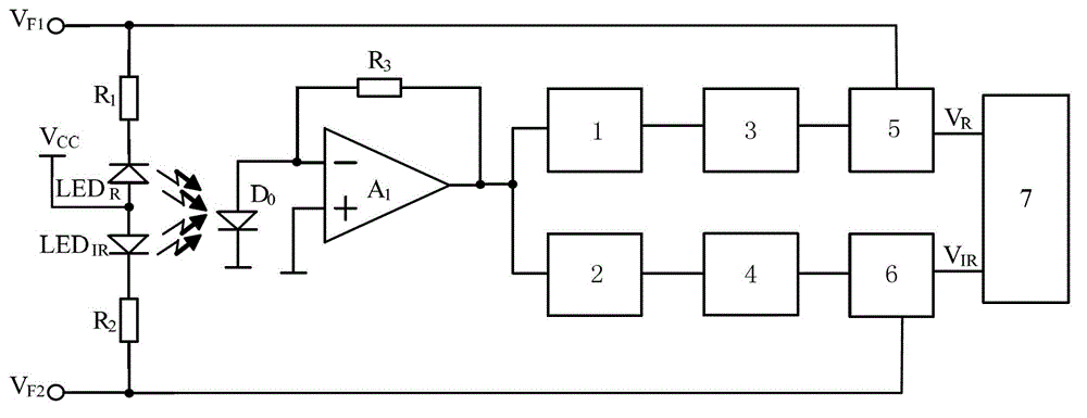
[0059] see figure 1 , a high-efficiency blood oxygen saturation detection circuit, including: a first resistor R 1 , the second resistor R 2 and photodiode D 0 ,

[0060] The first resistor R 1 One end of the input first sinusoidal signal V F1 , the first resistor R 1 The other ends are respectively connected to the first light-emitting diode LED R The cathode and the first frequency converter 5, the first light-emitting diode LED R The anode is connected to the power supply Vcc; the second resistor R 2 One end of the input second sinusoidal signal V F2 , the second resistor R 2 The other ends are respectively connected to the second light-emitting diode LED IR The cathode and the second frequency divider 6, the second light-emitting diode LED IR The anode of the power supply Vcc;

[0061] Photodiode D 0 The cathode is grounded, and the anode is respectively connected to the third resistor R 3 and the first operational amplifier A 1 The negative terminal of the ...

Embodiment 2

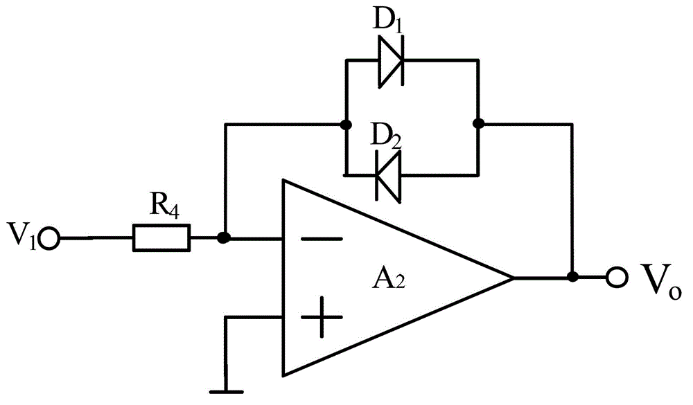
[0119] The difference between this embodiment and Embodiment 1 is only the specific structure of the frequency difference device, see Figure 6 , the frequency differencer includes: a fifth resistor R 5 and the sixth resistor R 6 ,

[0120] Fifth resistor R 5 One end of the input second signal source V 2 , the fifth resistor R 5 The other ends are respectively connected to the third diode D 3 anode of the fourth diode D 4 cathode of the third diode D 3 cathode and fourth diode D 4 The anode is connected to the third operational amplifier A at the same time 3 The output of V 0 , output photoplethysmography; the third diode D 3 Parallel capacitance C;

[0121] Sixth resistor R 6 One end of the input third signal source V 3 , the sixth resistor R 6 The other ends are respectively connected to the third diode D 3 The anode of the fourth diode D 4 cathode and the third op amp A 3 The negative polarity input terminal; the third operational amplifier A 3 The positiv...

Embodiment 3

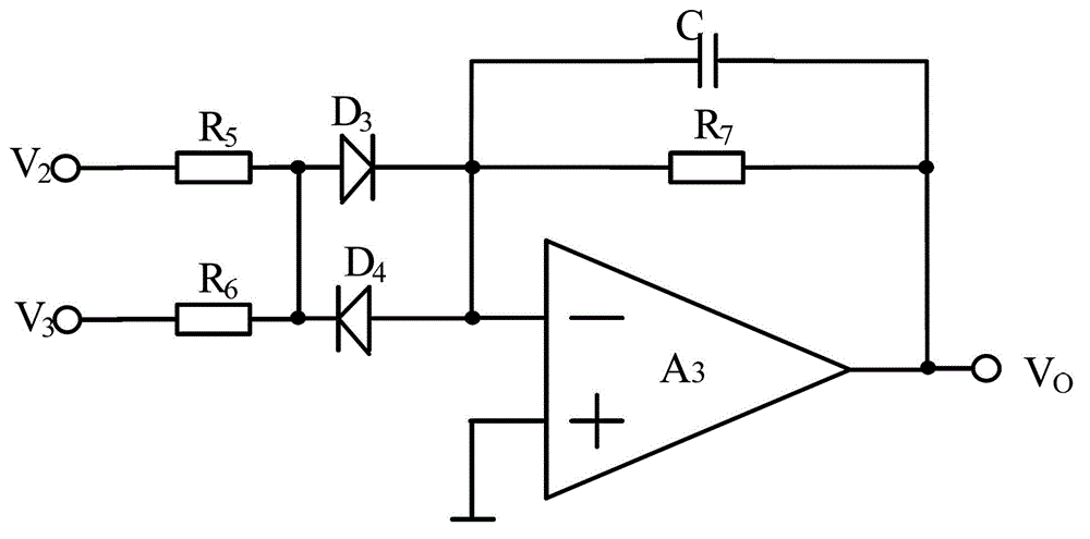
[0151] The difference between this embodiment and Embodiment 1 is only the specific structure of the frequency difference device, see Figure 7 , the frequency differencer includes: including: a fifth resistor R 5 and the sixth resistor R 6 ,

[0152] Fifth resistor R 5 One end of the input second signal source V 2 , the fifth resistor R 5 The other end of the seventh resistor R 7 One end of the seventh resistor R 7 The other end of the third operational amplifier A 3 The output of V 0 , output photoplethysmography;

[0153] Sixth resistor R 6 One end of the input third signal source V 3 , the sixth resistor R 6 The other ends are connected to the seventh resistor R 7 One end and the third operational amplifier A 3 The negative polarity input terminal; the third operational amplifier A 3 The positive polarity input terminal is grounded.

[0154] by right Figure 7 The analysis shows that the frequency difference device is an inverting operational amplifier type...


PUM


Abstract

The invention discloses an efficient blood oxygen saturation detection circuit; a first bandpass filter is sequentially connected with a first bidirectional logarithmic amplifier and a first difference frequency device and used for outputting first photoelectric volume pulse waves with the length of R; the second bandpass filter is sequentially connected with a second bidirectional logarithmic amplifier and a second difference frequency device and used for outputting second photoelectric volume pulse waves wit the length of IR; the first photoelectric volume pulse waves and the second photoelectric volume pulse waves are input into a controller, the controller is used for collecting and calculating, and outputting blood oxygen saturation. The bidirectional logarithmic amplifier formed by adopting an operational amplifier, and the difference frequency devices are taken as an efficient blood oxygen saturation detection circuit, the circuit is simple, the sensitivity is high, the manufacturability is excellent, the integration is easy, the amount of computation is lowered considerably and the blood oxygen saturation detection precision is improved, and the cost is lowered; by modifying resistance and capacitive value, the gain of the difference frequency devices can be changed, by selecting the models of the operational amplifiers, magnification treatment can be performed on photoelectric volume pulse waves, and various requirements in practical application can be met.

Description

technical field [0001] The invention relates to the field of electronic technology, in particular to a high-efficiency blood oxygen saturation detection circuit. Background technique [0002] The traditional blood oxygen saturation measurement method based on photoplethysmography usually uses special red light and infrared light diodes and photoelectric sensors to obtain photoplethysmography, and then obtains blood oxygen saturation through spectrum. [0003] In the process of realizing the present invention, the inventor finds that at least the following disadvantages and deficiencies exist in the prior art: [0004] In the process of the above operation, there are strict requirements on device parameters and measurement conditions. When the calculation is complicated and takes up a large number of CPU machines, the measurement cost is increased, the scope of practical application is limited, and the obtained blood oxygen saturation accuracy not tall. Contents of the inv...

Claims


Application Information

Patent Timeline
IPC IPC(8): A61B5/1455
Inventor 李刚贺建满林凌
Owner TIANJIN UNIV
Features
  • R&D
  • Intellectual Property
  • Life Sciences
  • Materials
  • Tech Scout
  • Unparalleled Data Quality
  • Higher Quality Content
  • 60% Fewer Hallucinations
Learn More