Check patentability & draft patents in minutes with Patsnap Eureka AI!

Difference frequency device based on operational amplifier

A technology of operational amplifiers and frequency difference devices, which is applied in the electronic field, can solve the problems of large combined frequency interference, unstable difference frequency signals, and large influence of discrete frequency difference devices, so as to reduce circuit costs, facilitate integration, The effect of simple structure

Inactive Publication Date: 2013-05-15
TIANJIN UNIV
View PDF4 Cites 0 Cited by
  • Summary
  • Abstract
  • Description
  • Claims
  • Application Information

AI Technical Summary

Problems solved by technology

[0004] 1) The mutual influence between the circuits of the above frequency difference device is serious, and the combined frequency interference is also relatively large, resulting in the instability of the obtained difference frequency signal;
[0005] 2) The above-mentioned difference frequency converter is greatly affected by the discreteness of component parameters, and the dynamic range of the signal that can be processed is small;
[0006] 3) The obtained difference frequency signal is an attenuated signal with low sensitivity, which is difficult to meet various needs in practical applications

Method used


Image

  • Difference frequency device based on operational amplifier
  • Difference frequency device based on operational amplifier
  • Difference frequency device based on operational amplifier

Examples


Embodiment 1

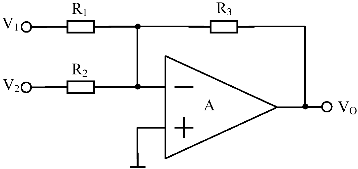
[0025] An operational amplifier-based difference frequency converter, see figure 1 , including: the first resistor R 1 and the second resistor R 2 ,

[0026] The first resistor R 1 One end of the input first signal source V 1 , the first resistor R 1 The other end of the third resistor R 3 One end of the third resistor R 3 The other end is connected to the output end of the operational amplifier A, and the output difference frequency signal voltage V o ;

[0027] The second resistor R 2 One end of the input second signal source V 2 , the second resistor R 2 The other ends are connected to the third resistor R 3 One end and the negative polarity input terminal of operational amplifier A; the positive polarity input terminal of operational amplifier A is grounded.

[0028] by right figure 1 The analysis shows that the frequency difference device is an inverting operational amplifier type frequency difference device,

[0029] Difference frequency signal voltage ...

Embodiment 2

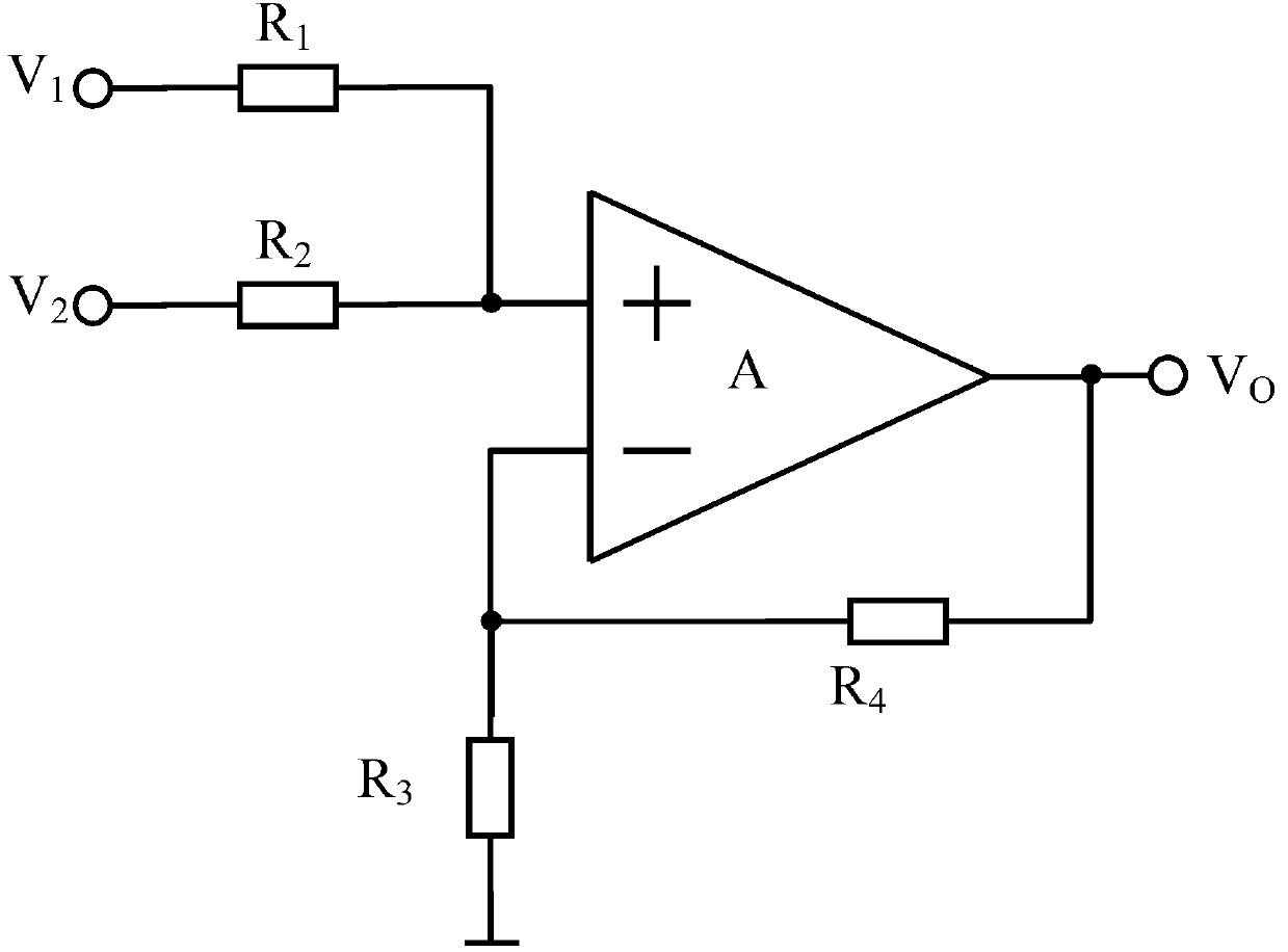
[0033] An operational amplifier-based difference frequency converter, see figure 2 , including: the first resistor R 1 and the second resistor R 2 ,

[0034] The first resistor R 1 One end of the input first signal source V 1 , the second resistor R 2 One end of the input second signal source V 2 , the first resistor R 1 the other end and the second resistor R 2 The other end of the operational amplifier is connected to the positive input terminal of the operational amplifier A; the negative input terminal of the operational amplifier A is connected to the third resistor R at the same time 3 and the fourth resistor R 4 One end; the third resistor R 3 The other end of the ground; the fourth resistor R 4 The other end is connected to the output end of the operational amplifier A, and the output difference frequency signal voltage V o .

[0035] by right figure 2 The analysis shows that the frequency difference device is a non-inverting operational amplifier type f...

Embodiment 3

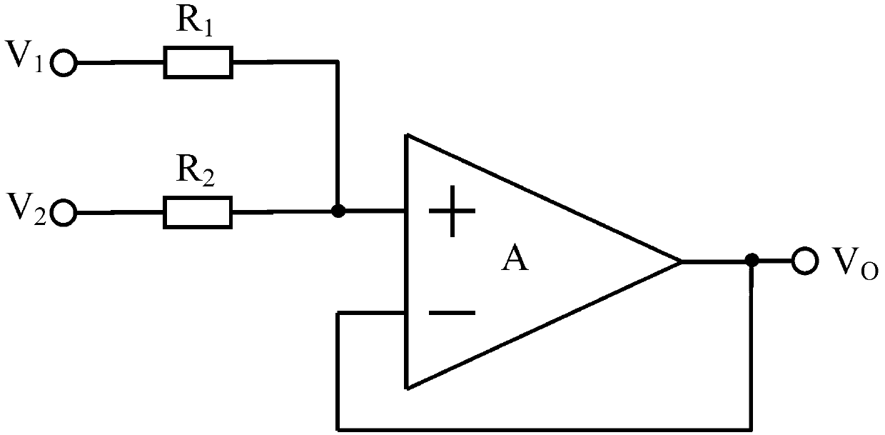
[0040] An operational amplifier-based difference frequency converter, see image 3 , including: the first resistor R 1 and the second resistor R 2 ,

[0041] The first resistor R 1 One end of the input first signal source V 1 , the second resistor R 2 One end of the input second signal source V 2 , the first resistor R 1 the other end and the second resistor R 2 The other end of the operational amplifier is connected to the positive input terminal of the operational amplifier A; the negative input terminal of the operational amplifier A is connected to the output terminal, and the difference frequency signal voltage V is output o .

[0042] by right image 3 The analysis shows that the frequency difference device is a frequency difference device of a follower-type operational amplifier,

[0043] Difference frequency signal voltage V o = K R 2 ...


PUM


Abstract

The invention discloses three kinds of difference frequency devices based on operational amplifiers. The difference frequency devices based on the operational amplifiers are composed of resistors and the operational amplifiers with low slew rate. According to the three kinds of the difference frequency devices, structures are simple, difference frequency signals which are stable and high in precision can be obtained conveniently, integration is completed easily, and circuit cost is reduced. Gains of the difference frequency devices are easy to change through modification of resistance value of the resistors, amplification management to the difference frequency signals can be achieved through selection of models of the operational amplifiers, and various demands in practical application are met.

Description

technical field [0001] The invention relates to the field of electronic technology, in particular to a frequency difference device based on an operational amplifier. Background technique [0002] The frequency difference device is a nonlinear device, and the frequency of the output signal is equal to the difference between the frequencies of the two input signals. The frequency difference devices in the prior art are usually diode frequency difference devices, balanced frequency difference devices and transistor frequency difference devices, all of which are composed of inductors and transformers. [0003] In the process of realizing the present invention, the inventor finds that at least the following disadvantages and deficiencies exist in the prior art: [0004] 1) The mutual influence between the circuits of the above frequency difference device is serious, and the combined frequency interference is also relatively large, resulting in the instability of the obtained dif...

Claims


Application Information

Patent Timeline
Patent Type & Authority Applications(China)
IPC IPC(8): H03F3/45
Inventor 李刚包磊林凌
Owner TIANJIN UNIV
Features
  • R&D
  • Intellectual Property
  • Life Sciences
  • Materials
  • Tech Scout
  • Unparalleled Data Quality
  • Higher Quality Content
  • 60% Fewer Hallucinations
Learn More