Rotary shear flow tray

A rotary shear, tray technology, applied in chemical/physical/physical chemical processes, dispersed particle separation, fractionation, etc., can solve the problems of short residence time, low tray efficiency, insufficient gas-liquid contact, etc. The effect of gas film and liquid film resistance, improving the driving force of mass transfer, and speeding up the renewal

Inactive Publication Date: 2013-06-12
沈宏
View PDF8 Cites 7 Cited by
  • Summary
  • Abstract
  • Description
  • Claims
  • Application Information

AI Technical Summary

Problems solved by technology

[0003] In order to solve the problem of short residence time of liquid on the tray and insufficient gas-liquid contact in the existing spray trays, the present invention proposes a long liquid residence time and high tray efficiency. Rotating Shear Flow Tray

Method used


Image

  • Rotary shear flow tray
  • Rotary shear flow tray
  • Rotary shear flow tray

Examples


Embodiment 1

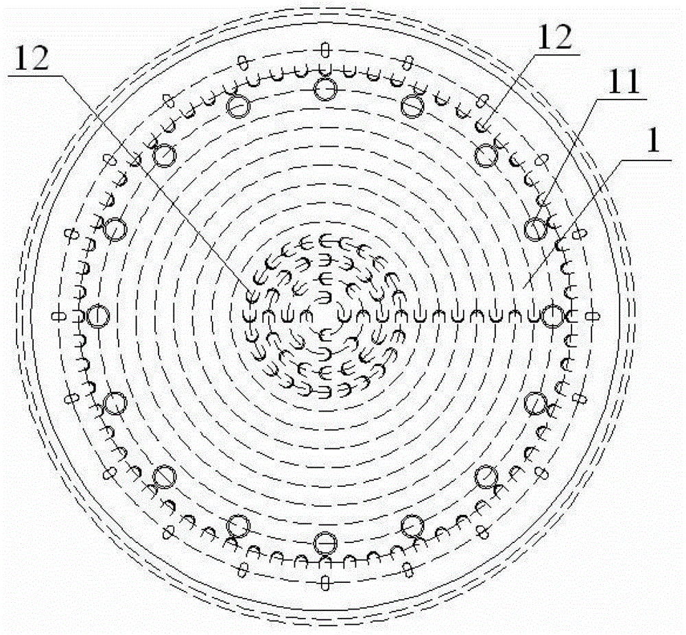
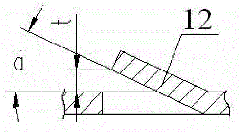
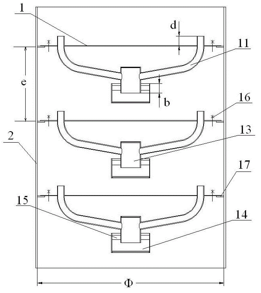
[0023] Embodiment 1 The rotary shear flow tray of the present invention includes a tray 1, on which a plurality of downcomers 11 and a plurality of spray holes 12 are arranged, and one end of the downcomer 11 is fixed On the outer ring of the tray 1, the other end extends toward the center of the tray 1 until it communicates with the central liquid collection pipe 13 below the tray 1. The liquid outlet of the central liquid collection pipe 13 is connected to the In the liquid receiving tank 14 below the liquid pipe 13, the downcomer 11 is arranged along the circumference of the tray 1 to form a circle of downcomer rings, and the downcomer 11 is fixed on the One end of the tray 1 is higher than the upper surface of the tray 1; the liquid receiving tank 14 is connected with the central liquid collecting pipe 13 through the lacing plate 15, and the outlet of the central liquid collecting pipe and the overflow port of the liquid receiving tank are used The liquid level difference ...

Embodiment 2

[0034] Embodiment 2 The difference between this embodiment and Embodiment 1 is that the inclined injection hole can be a tongue-shaped injection hole, and the rest of the implementation methods and structures are the same, taking the existing injection tray as an example (assuming all Macro-quantitative analysis based on a tray with a tower body diameter of 1 meter): deducting the liquid receiving area and the downcomer area, the longest path for the liquid to flow on the tray from the liquid receiving area to the downcomer area is about 0.75 meters, while The path length of the liquid from the liquid receiving area to the downcomer of the rotating shear flow tray is the sum of the concentric circular paths that flow from the liquid receiving area (tray center area) to the downcomer, that is It is about 10-15 meters, that is, the gas-liquid mass transfer time can be increased by more than ten times, and the number of circular paths n is determined by the number and arrangement...


PUM


Abstract

The invention provides a rotary shear flow tray which includes a tray. A plurality of downcomers and a plurality of spraying inclined holes are arranged on the tray, one end of each downcomer is fixed on a periphery of the tray, and the other end extends towards the centre of the tray until being communicated with a central liquid-collecting tube below the tray. A liquid outlet of the central liquid-collecting tube is communicated with a liquid-receiving groove arranged below the central liquid-collecting tube. The spraying inclined holes which regard the center of the tray as the center of a circle form multiple circles of concentric spraying inclined hole rings in a circumferential arrangement. Spraying holes of each spraying inclined hole ring which is arranged inside a circle of a downcomer tube ring are arranged at intervals in a clockwise or counterclockwise mode. The rotary shear flow tray has the advantages of 1) increasing a contact area of gas and liquid, accelerating the updating of two-phase surfaces of the gas and the liquid, and decreasing the resistance of a gas membrane and a liquid membrane; 2) strengthening eddy diffusion transmission; 3) prolonging the contact time of the gas and the liquid; 4) ensuring that the gas and the liquid are in a countercurrent contact for multiple times, preventing short-circuit, entrainment, and backmixing of the air and the liquid, and enhancing mass transfer driving force.

Description

technical field [0001] The invention relates to a rotating shear flow tray. Background technique [0002] Tray tower is one of the most widely used unit operation equipment in chemical production, mainly used in rectification, absorption and gas washing. Because it has the advantages of large production capacity, simple control, large operating flexibility, stable performance, and convenient maintenance and cleaning. Tray towers are divided into towers with different names due to the different forms of internal trays. At present, the common ones are (1) bubble cap tower, (2) sieve tray tower, (3) valve tower, (4) jet tray . So far, the existing injection towers have injection holes (such as tongue-shaped holes) in the same direction as the liquid flow on the tray (see below Figure 4 ), the gas is ejected through the tongue hole, and its component force along the horizontal direction pushes the liquid to flow. Since the maximum path of liquid flow on a certain tray is the...

Claims


Application Information

Patent Timeline
Patent Type & Authority Applications(China)
IPC IPC(8): B01D3/30B01D3/14B01D53/18B01J19/00B01J19/32
Inventor 沈宏
Owner 沈宏
Why Eureka
Try Eureka