Special blade for roughly processing large axial forge piece with V-shaped tool noses
A rough machining and blade technology, which is applied in the field of special blades for rough machining of large shaft forgings with V-shaped tool nose, can solve the problems of tool breakage failure, difficulty in chip breaking, knife-chip bonding, etc., and achieve accelerated breaking and enhanced breaking. chip performance, the effect of reducing cutting heat
- Summary
- Abstract
- Description
- Claims
- Application Information
AI Technical Summary
Problems solved by technology
Method used
Image
Examples
specific Embodiment approach 1
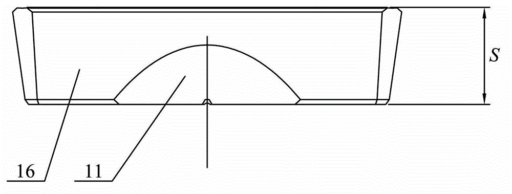
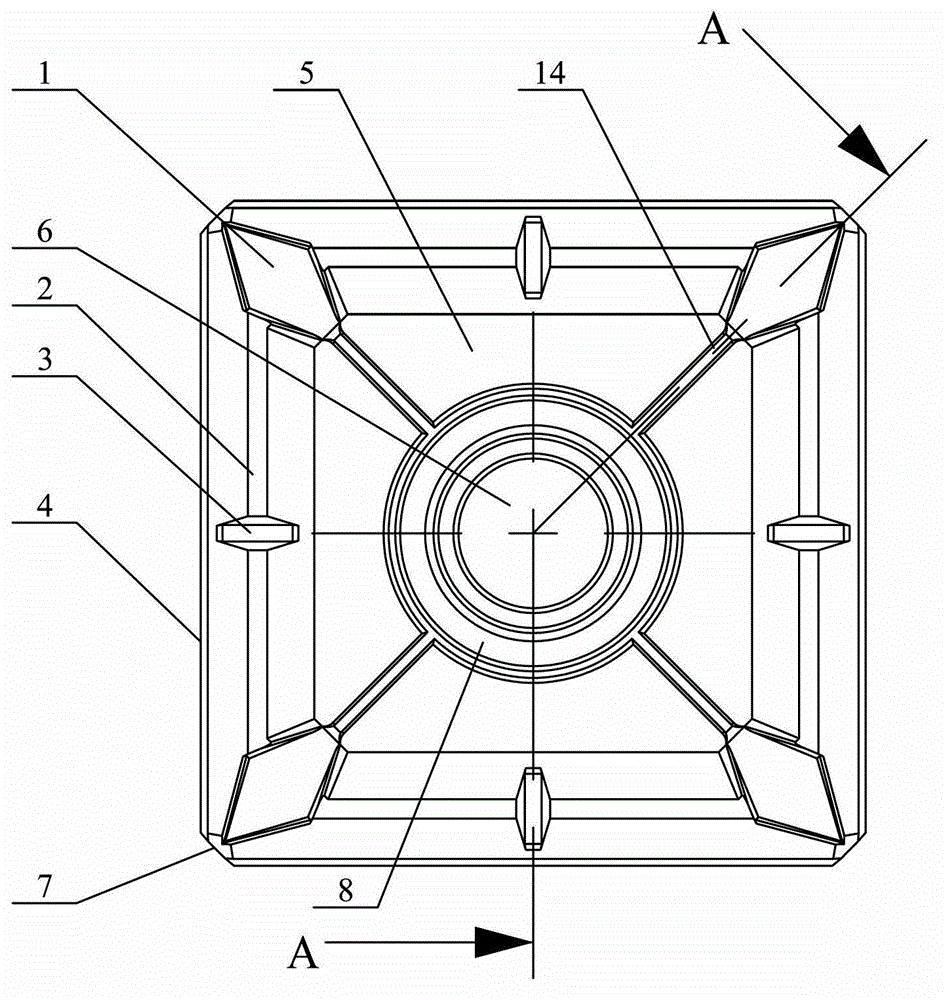
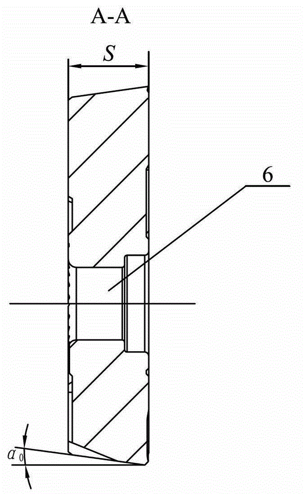
[0019] Specific implementation mode one: as Figure 1-Figure 5 As shown, the special blade for rough machining of large-scale shaft forgings with V-shaped tip in this embodiment, the shape of the blade is a square truss shape, the area of the bottom surface of the blade is smaller than the area of the rake face of the blade, and the four outer edges of the rake face of the blade Four negative chamfering cutting edges 4 are respectively processed on the edge, and a V-shaped tool tip 7 is processed at the intersection of each adjacent two negative chamfering cutting edges 4 of the blade, and the sharp corner of the V-shaped tool tip 7 is processed with a The angle bisector of this V-shaped knife point 7 is perpendicular to the facade, and the middle part of the blade rake face is provided with a raised platform 5 in the shape of a square truss, and the area of the raised platform 5 front surface is less than the area of the raised platform 5 bottom surfaces, and the blade...
specific Embodiment approach 2
[0020] Specific implementation mode two: combination Figure 4 Illustrate, on the bottom surface of the blade of the present embodiment, a square cooling groove 9 is arranged on the outside of the outer periphery of the fastening screw counterbore 6, and the bottom surface of the square cooling groove 9 is located on the outer periphery of the fastening screw counterbore 6. The center line heat dissipation groove 15 communicated with the square heat dissipation groove 9 is processed between the middle part of each outer edge of the blade bottom surface and the middle part of the groove edge corresponding to the square heat dissipation groove 9 . The undisclosed technical features in this embodiment are the same as those in the first embodiment.
specific Embodiment approach 3
[0021] Specific implementation mode three: combination figure 1 and Figure 4 It is explained that, on the four flanks 16 of the insert in this embodiment, the concave curved surface 11 is processed near the centerline cooling groove 15 located on the flanks 16 . The undisclosed technical features in this embodiment are the same as those in the second embodiment.
PUM
 Abstract
Description
Claims
Application Information
 - R&D
- Intellectual Property
- Life Sciences
- Materials
- Tech Scout
- Unparalleled Data Quality
- Higher Quality Content
- 60% Fewer Hallucinations
Browse by: Latest US Patents, China's latest patents, Technical Efficacy Thesaurus, Application Domain, Technology Topic, Popular Technical Reports.
© 2025 PatSnap. All rights reserved.Legal|Privacy policy|Modern Slavery Act Transparency Statement|Sitemap|About US| Contact US: help@patsnap.com


