
Hydraulically-driven vehicle chassis and construction machinery

A hydraulic transmission and vehicle technology, which is applied to vehicle components, control devices, transportation and packaging, etc., can solve problems such as the inability to guarantee the straight running of the vehicle, the narrow speed range of the vehicle, and the out-of-synchronization of the motor, which is conducive to changing the design and realizing Optimal matching, great starting acceleration effect

Inactive Publication Date: 2013-06-12
SANY HEAVY IND CO LTD (CN)
View PDF5 Cites 20 Cited by
  • Summary
  • Abstract
  • Description
  • Claims
  • Application Information

AI Technical Summary

Problems solved by technology

The disadvantage of hydrostatic transmission is low efficiency, especially in high-speed motor conditions, so the vehicles with hydrostatic transmission are mostly off-road vehicles that do not require high speed, such as hydrostatic transmission loaders and hydrostatic transmission vehicles. and hydraulic excavators
[0005] The existing hydrostatic transmission vehicle chassis has the following problems: 1. The hydraulic circuit is a closed system, and the heat dissipation of the vehicle at high speed is poor. By controlling the reversing valve, it is possible to change whether the hydraulic motor is connected to oil, so as to realize the switching between high and low speeds of the vehicle. , there is a pressure shock; 2. Each motor is controlled separately, and the two motors on the same axle wheel may be out of sync. If a single motor control fails during driving, the vehicle cannot be guaranteed to travel in a straight line; 3. The speed range of the vehicle is narrow , low top speed etc.

Method used


Image

  • Hydraulically-driven vehicle chassis and construction machinery
  • Hydraulically-driven vehicle chassis and construction machinery

Examples


Embodiment Construction

[0026] It should be noted that, in the case of no conflict, the embodiments of the present invention and the features in the embodiments can be combined with each other. The present invention will be described in detail below with reference to the accompanying drawings and examples.

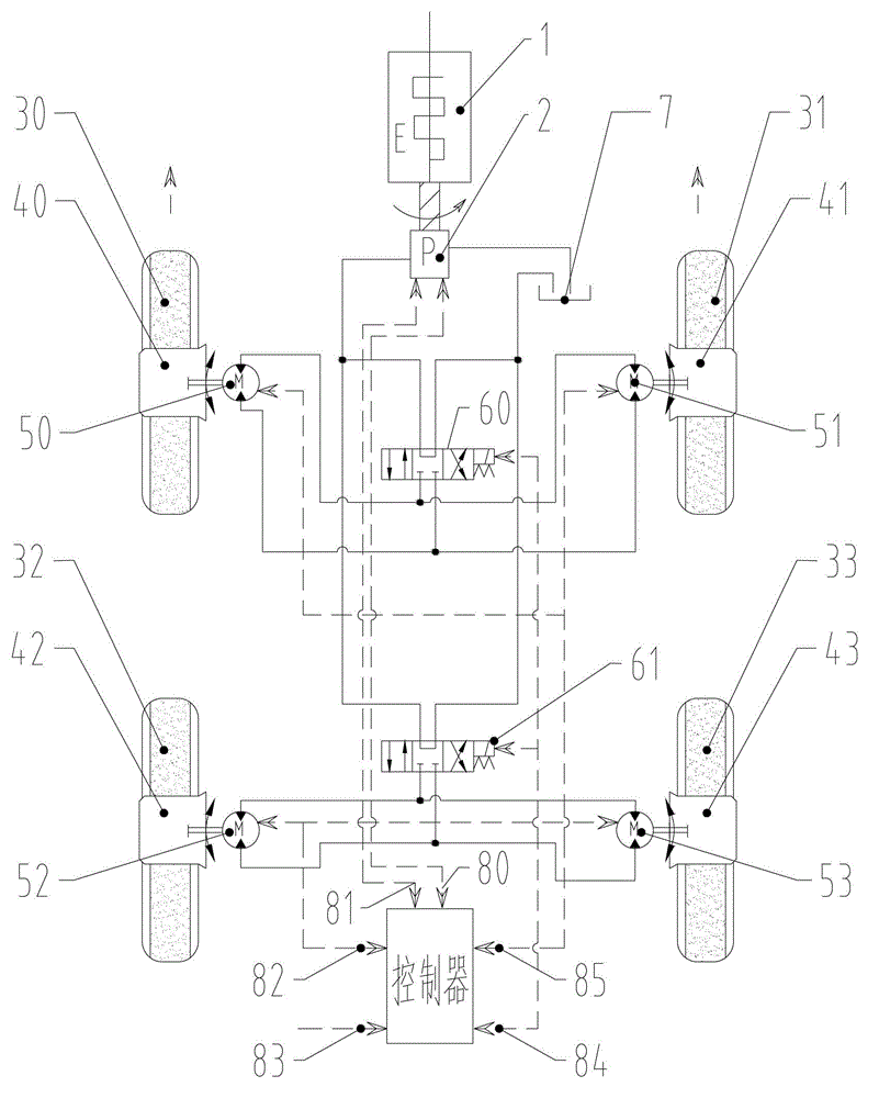
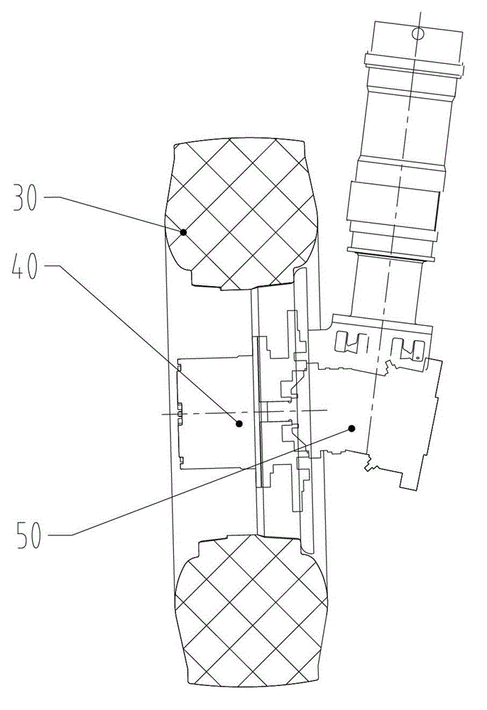
[0027] Such as figure 1 As shown, a hydraulically driven vehicle chassis includes: an engine 1, a variable displacement pump 2, four wheels, four variable displacement motors, two reversing valves, and a fuel tank 7. The engine 1 drives the variable displacement pump 2 to pump oil, and the variable displacement pump 2 Hydraulic oil is supplied to each variable motor through a reversing valve, and the oil return circuit of each variable motor communicates with the oil tank 7 . Four wheels comprise the left front wheel 30 and the right front wheel 31 positioned at the front axle, the left rear wheel 32 and the right rear wheel 33 positioned at the rear axle; The rotating right front variable moto...


PUM


Abstract

The invention discloses a hydraulically-driven vehicle chassis which comprises an engine, a variable pump, at least four wheels, at least four variable-displacement motors, at least two reversing valves and an oil tank, wherein the engine drives the variable pump to pump oil; the variable pump provides hydraulic oil to each variable-displacement motor through the reversing valves; each variable-displacement motor drives one wheel to rotate; each reversing valve controls an oil in / out oil line of two variable-displacement motors on the coaxial wheels; and the return oil line of each variable-displacement motor is communicated with the oil tank. The invention further provides construction machinery. According to the invention, a hydraulic return circuit is an opened system, and the hydraulic system has good radiating performance, and small pressure impact. The vehicle speed can be improved through controlling the variable pumps and the discharge capacity of the variable-displacement motors, and vehicle speed adjustment range can be further expanded as some variable-displacement motors are reduced to zero in discharge capacity, so that the starting acceleration is large and the speed regulation range is wide.

Description

technical field [0001] The invention relates to the field of engineering machinery, in particular to a hydraulic transmission vehicle chassis and engineering machinery. Background technique [0002] At present, some special engineering vehicles are often equipped with special equipment, have special operation functions and undertake transportation tasks, such as fire trucks, concrete pump trucks, truck cranes, etc. These special-purpose vehicles are mainly used as special-purpose equipment for operation, but their mobility requirements as a vehicle transportation function are getting higher and higher. % or more), more attention should be paid to the vehicle's starting acceleration and maneuverability in narrow places. These operating conditions require this type of special-purpose vehicle to have the characteristics of high-speed driving of road vehicles and good micro-controllability and flexibility of off-road vehicles. [0003] Traditional road vehicles mostly use mecha...

Claims


Application Information

Patent Timeline
IPC IPC(8): B60K17/10B60K17/14
Inventor 易小刚董新建罗彪
Owner SANY HEAVY IND CO LTD (CN)
Learn More