Device for measuring high-energy laser energy

A high-energy laser and energy measurement technology, which is applied in measuring devices, optical radiation measurement, radiation pyrometry, etc., can solve problems such as surface damage of absorbers, increased structural complexity and cost, and increased system complexity. Improve the anti-laser damage threshold, reduce the average power density, and increase the effect of laser irradiation area

Active Publication Date: 2015-05-27
NORTHWEST INST OF NUCLEAR TECH
View PDF2 Cites 0 Cited by
  • Summary
  • Abstract
  • Description
  • Claims
  • Application Information

AI Technical Summary

Problems solved by technology

[0003] In the measurement of high-energy laser energy in the existing total absorption energy meter, the light-receiving surface of the absorber has to bear all the long-term laser irradiation, and its ability to resist laser damage and destruction will become its technical bottleneck. Currently, the commonly used methods are: ( 1) Water circulation conducts heat and transfers heat to the outlet as soon as possible. This solution can reduce the temperature rise of the absorber after thermal balance, but it cannot solve the damage to the absorber surface when the laser irradiates the absorber, and needs to be added in the energy measurement device. Circulating waterways will inevitably increase the complexity and cost of the structure; (2) Sputtering anti-laser radiation films such as silicon carbide on the surface of the absorber, this solution has a very limited ability to increase the damage threshold and increases the complexity of the system

Method used


Image

  • Device for measuring high-energy laser energy
  • Device for measuring high-energy laser energy
  • Device for measuring high-energy laser energy

Examples


Embodiment Construction

[0032] The present invention will be further described in detail below in conjunction with the accompanying drawings and specific embodiments.

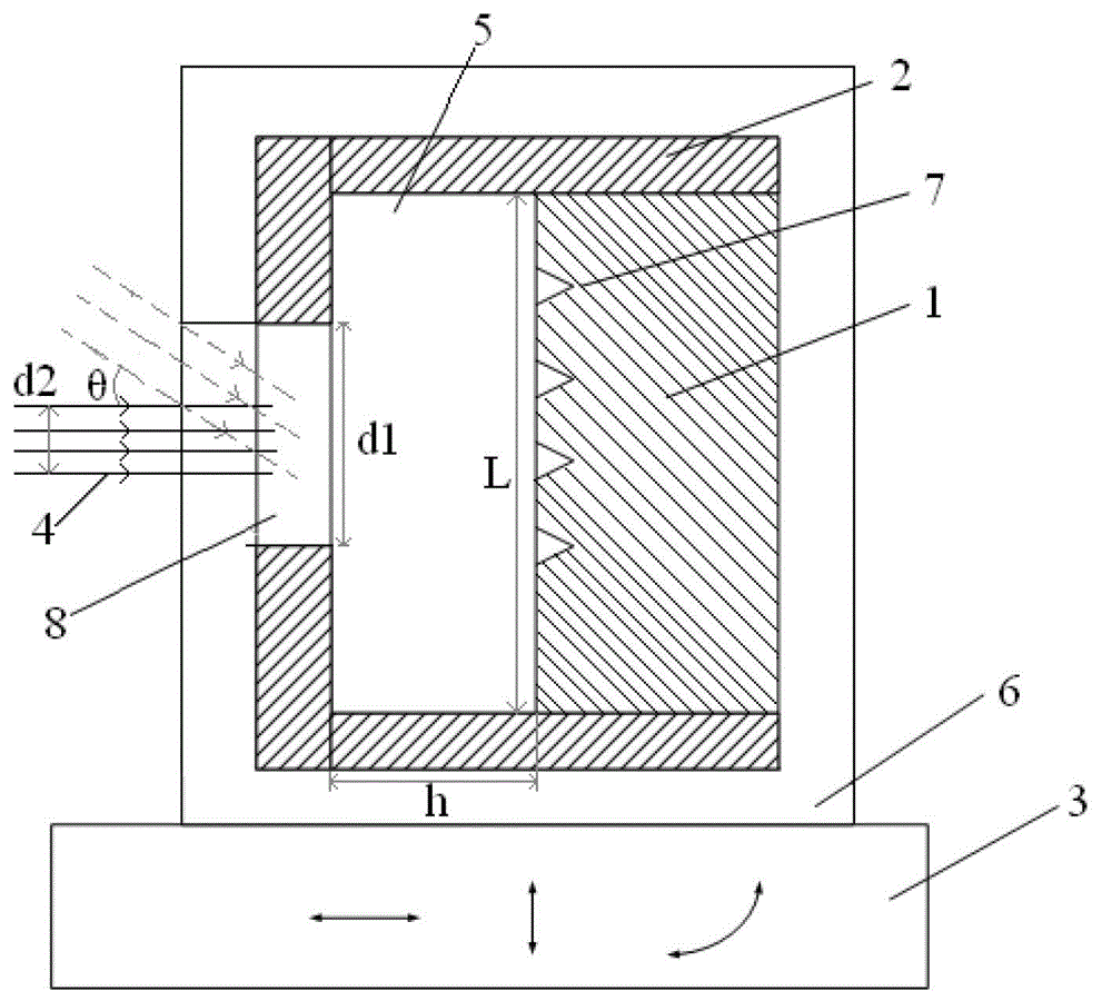
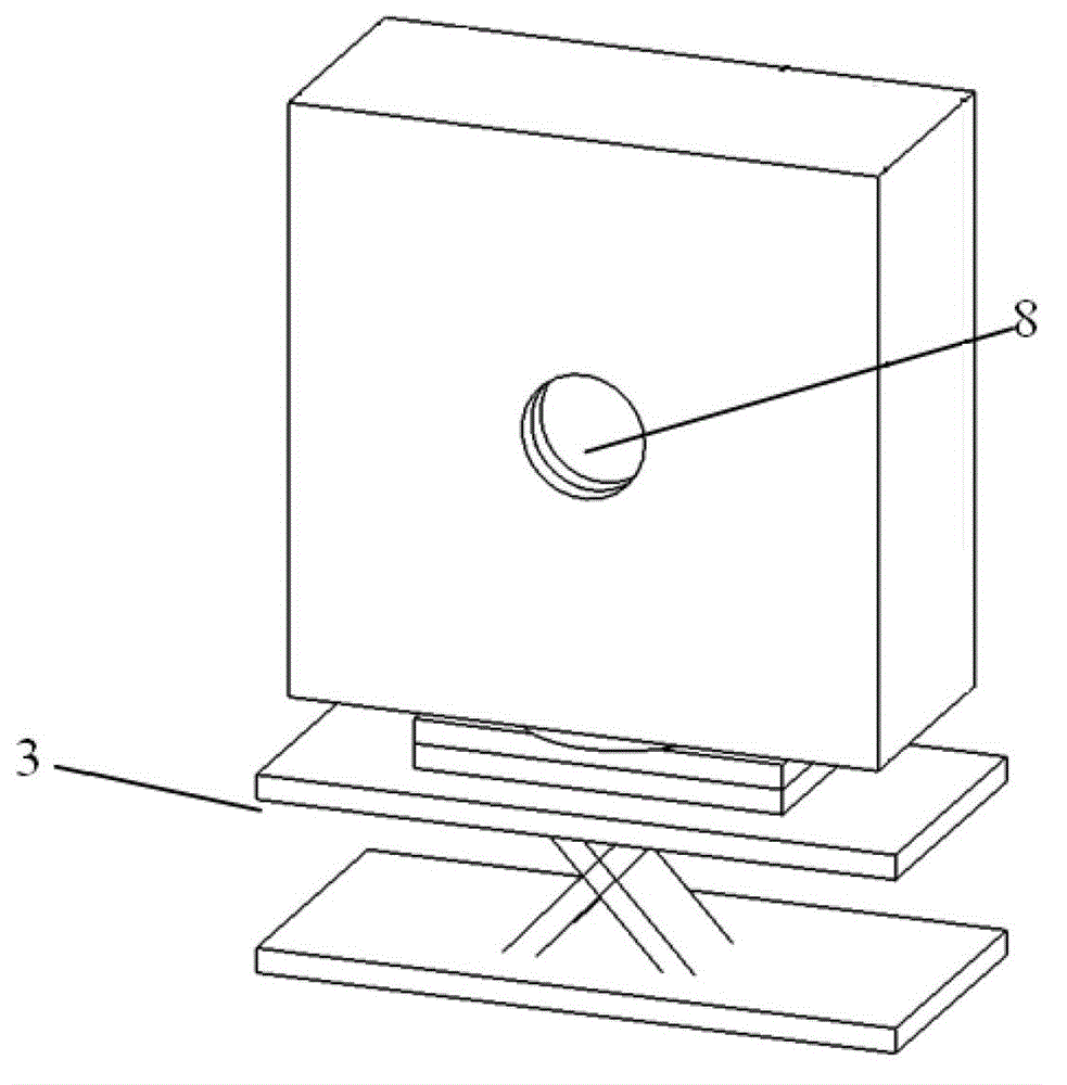
[0033] The present invention provides a laser energy measuring device with a high destruction threshold. The attitude adjustment unit 3 is used to adjust the position of the laser irradiation surface of the heat absorber 1 of the energy measuring device, so as to avoid that only the local surface of the heat absorber 1 is subjected to damage in conventional measurement. The damage of the absorber caused by strong light irradiation greatly reduces the average laser power density irradiated on the surface of the heat absorber 1 and increases the anti-laser damage threshold of the absorber.

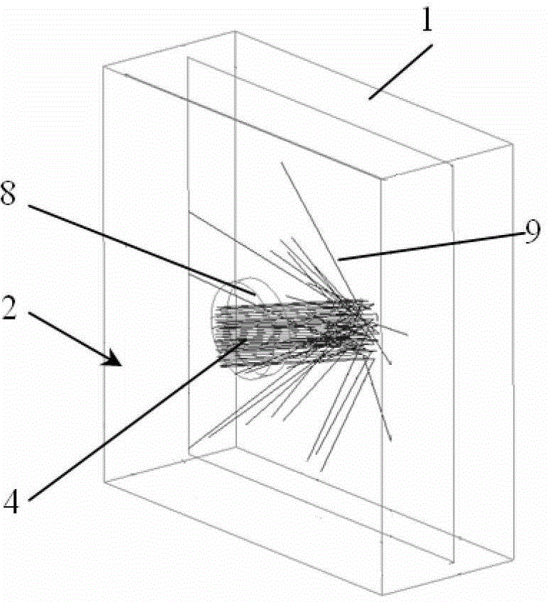
[0034] Such as figure 1 As shown, the high-energy laser energy measurement device includes a heat absorber 1, a collection cover 2, a temperature measurement unit, and a temperature acquisition and processing unit. The temperature acquisition and pr...


PUM


Abstract

The invention discloses a device for measuring high-energy laser energy. The device for measuring the high-energy laser energy comprises a heat absorption body, a collection cover, a temperature measuring unit and a temperature acquisition and processing unit, wherein the collection cover is arranged on the exterior of the heat absorption body; an airtight cavity is formed between the collection cover and a light-showing face of the heat absorption body; the internal surface of a cavity body of the airtight cavity is treated as a diffusely reflecting surface; the temperature measuring unit is arranged on the heat absorption body and the collection cover; a light pass hole is formed in the direction of the light-showing face of the collection cover; a posture adjustment unit is arranged below the collection cover; and during the process of emitting light, the horizontal position, the elevation position and the incident angle about the incidence of high-energy laser to the heat absorption body can be changed. The device for measuring the high-energy laser energy adopts a mode that a laser beam circularly scans the surface of the heat absorption body, so that the partial surface of the heat absorption body is prevented from persistently bearing strong laser irradiation, the power density of average laser irradiated onto the surface of the heat absorption body is decreased, and a laser damage resistance threshold value of a measuring system is improved.

Description

technical field [0001] The invention relates to a device for measuring the energy of a photothermal high-energy laser, in particular to a device suitable for absolute measurement of a long-time, high-energy high-energy laser. Background technique [0002] In the measurement of high-energy laser parameters, the total laser energy is the most basic and important index parameter. It is often measured by photothermal method, that is, the laser is incident on the absorber made of graphite and other materials, and the absorber absorbs the energy of the incident laser and It is converted into its own temperature rise, and the total energy of the high-energy laser is calculated by measuring the temperature rise. With the development of high-energy laser technology, high-power, long-light-emitting lasers have become the direction of active development in various countries. At present, lasers with megawatts of light output and minute-level light output will soon become possible. How t...

Claims


Application Information

Patent Timeline
Patent Type & Authority Patents(China)
IPC IPC(8): G01J5/58G01J5/02
Inventor 王振宝冯国斌陈绍武杨鹏翎叶锡生
Owner NORTHWEST INST OF NUCLEAR TECH
Why Eureka
Try Eureka