Method for detecting working point of current transformer under direct current magnetic biasing condition

A technology of current transformer and DC bias, which is applied in the direction of the magnitude/direction of the magnetic field, instruments, and measuring electricity, and can solve the problems of one-way deviation of the main magnetic flux, high saturation of the iron core, and distortion of the excitation current.

Active Publication Date: 2013-06-12
STATE GRID JIANGSU ELECTRIC POWER CO ELECTRIC POWER RES INST +2
View PDF4 Cites 13 Cited by
  • Summary
  • Abstract
  • Description
  • Claims
  • Application Information

AI Technical Summary

Problems solved by technology

According to research, under normal circumstances, a small excitation current can generate rated working magnetic flux. At this time, if a certain amount of DC enters the current transformer, the generated DC magnetic flux is much greater than the rated magnetic flux. If the two parts of the magnetic flux are directly Superposition, the main magnetic flux will be greatly shifted in one direction, resulting in high saturation of the iron core and serious distortion of the excitation current
For the DC bias phenomenon of current transformers, it is easy to misunderstand that the magnetic flux of the current transformer under the DC bias is equal to the DC magnetic flux generated by the DC current entering the current transformer directly superimposed on the original AC magnetic flux, Produce DC Bias Effect

Method used


Image

  • Method for detecting working point of current transformer under direct current magnetic biasing condition
  • Method for detecting working point of current transformer under direct current magnetic biasing condition
  • Method for detecting working point of current transformer under direct current magnetic biasing condition

Examples


Embodiment Construction

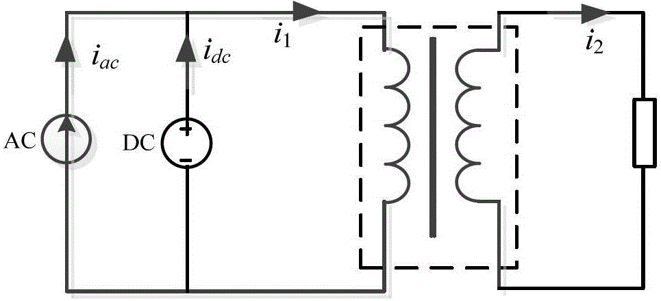
[0028] The numerical calculation method for determining the operating point of the current transformer under the condition of DC bias: the primary side current of the current transformer is connected in parallel with the fundamental AC current source and the DC current source to simulate the bias phenomenon caused by the joint action of the AC current and the DC current, press figure 1 The shown circuit analyzes and calculates the magnetization characteristics and excitation current of the current transformer under DC bias.

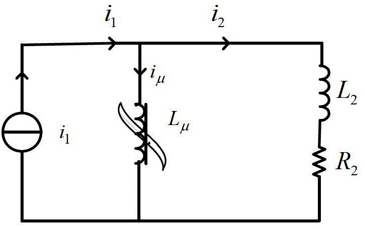
[0029] In order to simplify the analysis, according to the equivalent circuit of the current transformer, the primary winding is converted to the secondary side, the iron core loss is ignored, the excitation branch is a nonlinear inductance circuit, and L μ It means that the leakage inductance and resistance of the primary winding are negligible for the primary current, and the resistance and leakage inductance of the secondary winding are combined with t...


PUM


Abstract

The invention discloses a method for detecting a working point of a current transformer under a direct current magnetic biasing condition. The method comprises the following steps of determining alternating current magnetic flux of the current transformer by a numerical integration algorithm; superposing one direct current magnetic flux on the alternating current magnetic flux, calculating a corresponding exciting current instantaneous value and a direct current exciting current average value according to a magnetizing curve of an iron core, and calculating the direct current magnetic flux of the iron core of the current transformer by utilizing an iterative approximation method to determine the characteristic quantity associated with the working point of the current transformer under the direct current magnetic biasing condition. The method disclosed by the invention can be used for calculating and determining the characteristic quantities of the sizes of the alternating current magnetic flux and the direct current magnetic flux of the iron core of the current transformer under the direct current magnetic biasing condition, the value of exciting current, the values of alternating current exciting current and direct current exciting current, the current transformer secondary current and the like associated with the working point of the current transformer.

Description

technical field [0001] The invention relates to a numerical calculation method for determining the working point of a current transformer under the condition of DC bias, including a calculation algorithm of the magnetic flux of the iron core of the current transformer and a system platform for detecting the working point of the current transformer, and belongs to the technical field of electric power automation. Background technique [0002] The distribution of DC potential in the earth may be formed by the operation of the single pole ground return line of the HVDC power transmission system or the solar magnetic storm, so that the DC current enters the AC grid from the transformer directly grounded at the neutral point, resulting in the DC bias magnetization of the current transformer of the AC system. DC bias may speed up the protection of current transformers, and the larger the bias current is, the faster the current transformers will saturate. [0003] The research on t...

Claims


Application Information

Patent Timeline
Patent Type & Authority Applications(China)
IPC IPC(8): G01R31/00G01R33/02
Inventor 李鹏黄浩声张佳敏王忠东袁宇波
Owner STATE GRID JIANGSU ELECTRIC POWER CO ELECTRIC POWER RES INST
Why Eureka
Try Eureka