Synchronous belt drive rotary prism device

A technology of rotating prisms and synchronous belts, applied in installation, optics, instruments, etc., can solve the problems of difficult to eliminate the return error and the existence of meshing gaps, and achieve the effect of compact structure, guaranteed reliability and flexible use.

Inactive Publication Date: 2013-06-12
TONGJI UNIV
View PDF7 Cites 26 Cited by
  • Summary
  • Abstract
  • Description
  • Claims
  • Application Information

AI Technical Summary

Problems solved by technology

[0011] In the prior technology (Patented by Li Anhu et al., "A prism mechanical device for coarse and fine two-level scanning"), the rotating motor drives the prism and the inner and outer mirror frame assembly

Method used


Image

  • Synchronous belt drive rotary prism device
  • Synchronous belt drive rotary prism device
  • Synchronous belt drive rotary prism device

Examples


Embodiment 1

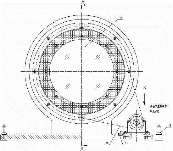
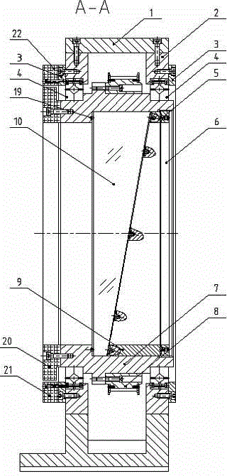
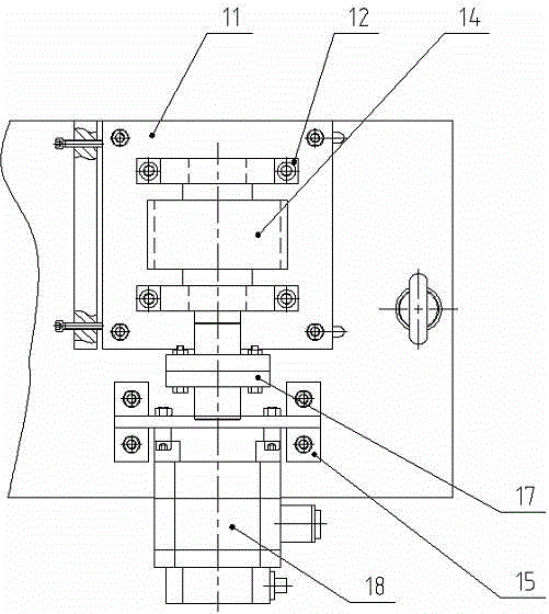
[0037] see Figure 1-Figure 4 as shown, figure 1 It is a front view of the overall structure of the rotating prism device of the present invention, figure 2 is the A-A sectional structure diagram of the overall structure of the device, image 3 for figure 1 Partial view of K direction, Figure 4 It is a structural diagram of the mirror frame and the scanning mirror assembly of the present invention. Such as Figure 4 As shown, the O-ring 19 is first placed in the circular groove on the shoulder of the mirror frame 7, and the structure of the mirror frame 7 is as follows Figure 8 Shown, put into wedge prism 10 then, the shape of wedge prism 10 is as follows Figure 9As shown, the vertical surface of the wedge prism 10 is not in direct contact with the shoulder of the mirror frame 7, but is pressed by a rubber O-ring to ensure that the wedge prism 10 is not damaged or worn. The other side of the wedge-shaped prism 10, that is, the wedge-shaped surface, is axially compr...


PUM


Abstract

The invention relates to a synchronous belt drive rotary prism device, which comprises a mirror frame and scanning frame assembly, a synchronous belt mechanism, rotary encoder assemblies and a machine seat assembly, wherein the machine seat assembly comprises a machine seat and two machine seat inserts; the mirror frame and scanning frame assembly comprises a rubber pad, a prism check ring, a mirror frame, a big pulley, a wedge-shaped check ring and a wedge-shaped prism; the synchronous belt mechanism comprises a small pulley axle support, a small bearing pressing block, a small pulley axle, a motor support, a synchronous belt, a coupling and a servo motor; and two sets of rotary encoder assemblies are arranged and respectively comprise an encoder rotary ring, a first reading head and a second reading head. According to the synchronous belt drive rotary prism device provided by the invention, the center distance between two synchronous pulleys is adjustable within limits; the strain of the synchronous belt can be conveniently adjusted to ensure transmission reliability; the structure is compact; and the arrangement is flexible.

Description

technical field [0001] The invention relates to an optical transmission system, in particular to a synchronous belt driven rotary prism device. Background technique [0002] The rotating prism scanning mechanism has a wide range of applications in dynamic optical tracking, and can accurately realize the alignment of the optical path, the tracking of the measured object, and the compensation and correction of the beam pointing error. [0003] Common rotary drive methods are: [0004] (1) Gear transmission [0005] The prior technology (Zu Jifeng and other patents, application number 03129234.8, application date June 13, 2003 "Satellite trajectory optical simulation device") proposes to use a motor group with a gear transmission to realize different motion combinations of the rotating double prism, and realize the simulation of satellite relative motion. exercise requirements. However, the proposed motor combination drive scheme and control system are complex, and there are...

Claims


Application Information

Patent Timeline
IPC IPC(8): G02B26/10G02B7/18
Inventor 李安虎高心健
Owner TONGJI UNIV
Why Eureka
Try Eureka