
Manufacturing method of color film substrate, color film substrate and display device

A color filter substrate and manufacturing method technology, applied in optics, instruments, nonlinear optics, etc., can solve the problems of wasting materials, increasing manufacturing costs, increasing process steps and time, and reducing the number of times and time, reducing manufacturing costs, simple craftsmanship

Inactive Publication Date: 2013-06-12
BOE TECH GRP CO LTD
View PDF5 Cites 7 Cited by
  • Summary
  • Abstract
  • Description
  • Claims
  • Application Information

AI Technical Summary

Problems solved by technology

However, when using this method to make a color filter layer, compared with the second method, it not only increases the number of masks, but also increases the number of exposure and development processes.
For example, if the color filter layer includes a red filter layer, a green filter layer, and a blue filter layer, two mask plates and six exposure and development processes are required when using this method to make the color filter layer, so the same method 1. Compared with this method, the process steps and time are increased, and the manufacturing cost is improved
[0009] At the same time, in the color filter layer made by the above method, since the thickness of the color filter layer corresponding to the transmission area is greater than the thickness of the color filter layer corresponding to the reflection area, the color filter layer on the color filter substrate corresponding to the color filter layer is increased. Step difference, in order to eliminate the step difference, the flat protective layer in the color filter substrate corresponding to the color filter layer is thicker than the flat protective layer in the color filter substrate in the existing transmissive display or reflective display. There is a disadvantage of wasting material

Method used


Image

  • Manufacturing method of color film substrate, color film substrate and display device
  • Manufacturing method of color film substrate, color film substrate and display device
  • Manufacturing method of color film substrate, color film substrate and display device

Examples


Embodiment 1

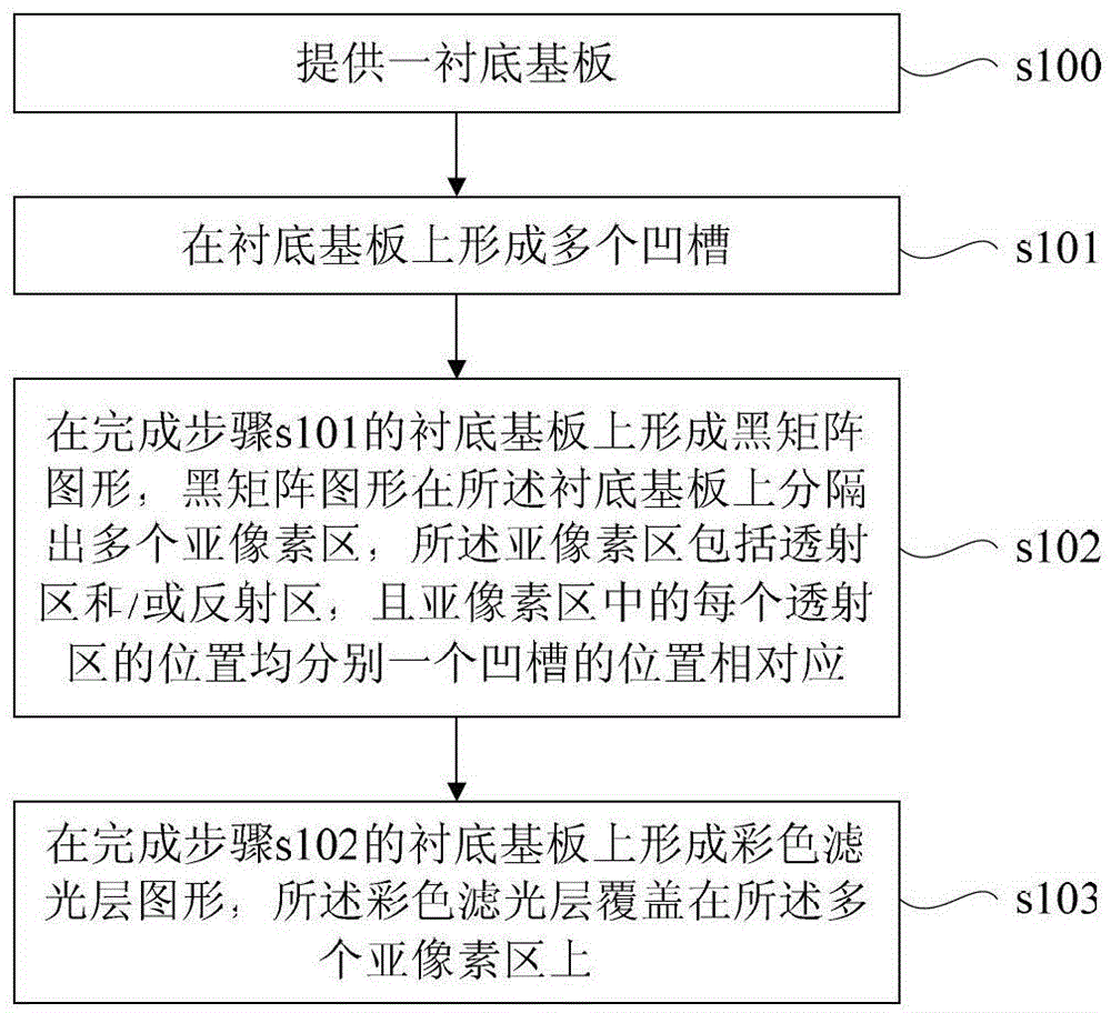
[0046] Such as figure 1 As shown, this embodiment provides a method for manufacturing a color filter substrate, including the following steps:

[0047] s100. Providing a base substrate.

[0048] The base substrate should be clean and free of dust and impurity ions. The base substrate can be transparent substrates such as glass substrates, quartz substrates, and plastic substrates.

[0049] s101. Forming a plurality of grooves on the base substrate.

[0050] The method for forming the plurality of grooves specifically includes: coating a layer of photoresist on the base substrate, exposing and developing the photoresist by using a mask to form a photoresist layer on the base substrate. The glue retaining area and the photoresist removal area, wherein, the photoresist removal area corresponds to the area of ​​the plurality of grooves, then the exposed base substrate is etched, and finally the remaining photoresist is removed by the photoresist stripping process. The resist i...

Embodiment 2

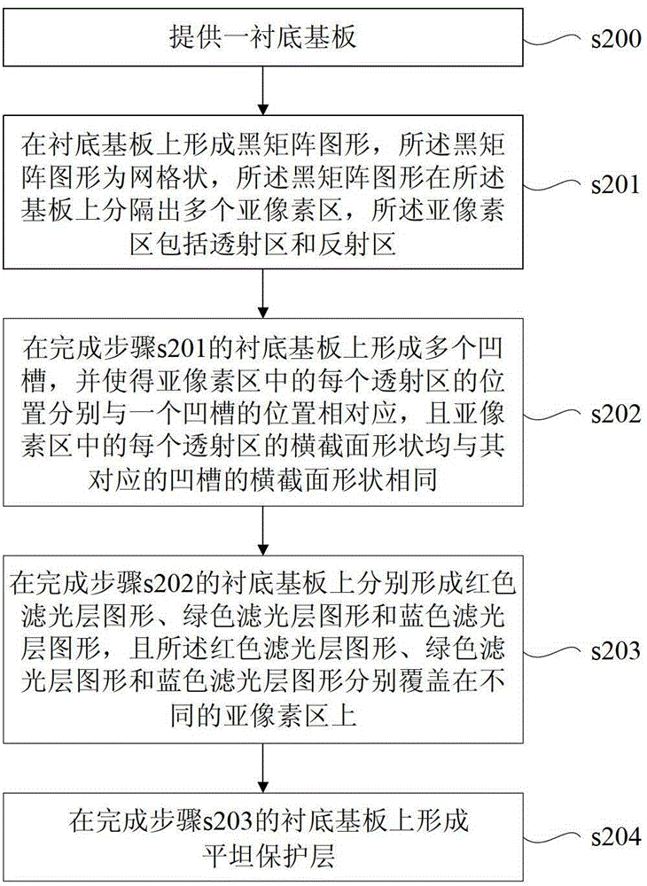
[0062] Such as figure 2 As shown, this embodiment provides a method for manufacturing a color filter substrate, including the following steps:

[0063] s200. Providing a base substrate.

[0064] The base substrate should be clean and free of dust and impurity ions. The base substrate can be transparent substrates such as glass substrates, quartz substrates, and plastic substrates.

[0065] s201. Forming a black matrix pattern on the base substrate, the black matrix pattern is grid-like, and the black matrix pattern separates a plurality of sub-pixel regions on the base substrate, and the sub-pixel regions include a transmission region and reflective areas. The structure of the color filter substrate that completes this step is as follows image 3 As shown, in this embodiment, the reflective region II in the sub-pixel region is located around and surrounds the transmissive region I, so as to achieve a better display effect.

[0066] Specifically, taking metal materials as...

Embodiment 3

[0094] This embodiment provides a color filter substrate, including a base substrate, a black matrix disposed on the base substrate, and a color filter layer. The pattern formed by the black matrix is ​​separated into multiple The sub-pixel area, the color filter layer is covered on the plurality of sub-pixel areas, the sub-pixel area includes a transmission area and / or a reflection area, a plurality of grooves are arranged on the base substrate, and the sub-pixel The position of each transmissive area in the zone corresponds to the position of a groove respectively.

[0095] Said that the sub-pixel area includes a transmission area and / or a reflection area means: each sub-pixel area includes both a transmission area and a reflection area; or, some sub-pixel areas only include a transmission area, and some sub-pixel areas only include a transmission area. Includes reflective areas. Of course, no matter what the case is, only the position corresponding to the transmission area...


PUM

PropertyMeasurementUnit
depthaaaaaaaaaa

Abstract

The invention provides a manufacturing method of a color film substrate, which comprises the steps that a black matrix figure and a color filter layer figure are formed on a backing substrate; the black matrix figure is divided into a plurality of sub pixel areas on the backing substrate; the sub pixel areas are covered with a color filter layer; the sub pixel areas comprise transmission areas and / or reflecting areas; before the color filter layer figure is formed, a plurality of grooves are formed in the backing substrate; and positions of the transmission areas in the sub pixel areas correspond to those of the grooves respectively. Correspondingly, the invention provides the color film substrate manufactured by the manufacturing method, and a display device comprising the color film substrate. With the adoption of the manufacturing method of the color film substrate, a color coordination effect can be achieved, process times can be reduced, and the thickness of a flat protective layer can be reduced.

Description

technical field [0001] The present invention relates to the technical field of liquid crystal display, in particular to a manufacturing method of a color filter substrate, a color filter substrate manufactured by the manufacturing method, and a display device including the color filter substrate. Background technique [0002] Since the liquid crystal display is a non-self-luminous display, it is necessary to configure a light source (such as a backlight source, a front light source or an external light source) for the display panel in order to display images. According to different utilization methods of light sources, liquid crystal displays can be divided into transmissive displays, transflective displays, and reflective displays. Among them, the transflective display has gradually attracted attention because it can utilize the light emitted by the external light source and the backlight source at the same time, and has a good display effect in the outdoor sunlight environ...

Claims


Application Information

Patent Timeline
Patent Type & Authority Applications(China)
IPC IPC(8): G02F1/1335G02B5/20
CPCG02F1/133512G02F1/133516G02B5/201G02B5/20G02F1/133514
Inventor 齐永莲舒适惠官宝
Owner BOE TECH GRP CO LTD
Learn More