Long-contact time micro-electromechanical universal inertia switch and manufacturing method for same

A contact time, inertia switch technology, applied in the direction of electrical switches, circuits, electrical components, etc., can solve the problems that the circuit cannot be reliably connected, short, and the contact time of the movable electrode and the fixed electrode is short, so as to improve the anti-interference performance. and reliability, extended contact time, reliable switching performance

Inactive Publication Date: 2013-06-12
SHENYANG LIGONG UNIV
View PDF3 Cites 14 Cited by
  • Summary
  • Abstract
  • Description
  • Claims
  • Application Information

AI Technical Summary

Problems solved by technology

However, due to the extremely short moment of collision, the contact time between the movable electrode and the fixed electrode is too

Method used


Image

  • Long-contact time micro-electromechanical universal inertia switch and manufacturing method for same
  • Long-contact time micro-electromechanical universal inertia switch and manufacturing method for same

Examples


Embodiment Construction

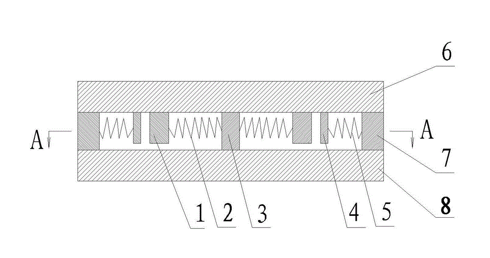
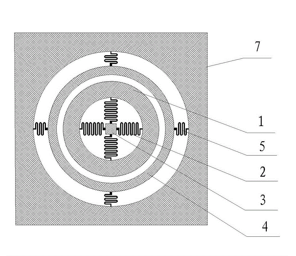
[0011] see figure 1 , which includes an upper cover plate 6, a lower cover plate 8 and a silicon chip intermediate structure layer, the said upper cover plate is a silicon plate; see figure 2 , the middle structure layer of the silicon wafer is, with the anchor point 3 as the center of the circle, there are ring-shaped quality frame 1, ring-shaped outer electrode 4 and anchor area 7 in sequence, and the anchor area is in the shape of a plane frame with an outer square and an inner circle, wherein the anchor area and the anchor point Bonded with the upper and lower cover plates, the four outer springs 5 ​​(constituting the outer spring frame) are arranged in a cross shape, and the two ends of each outer spring are respectively fixed between the anchor area and the ring-shaped outer electrode, and the four inner springs 2 ( The inner spring frame) is arranged in a cross shape, and the two ends of each inner spring are respectively fixed on the annular mass frame and the anchor ...


PUM


Abstract

The invention provides a long-contact time micro-electromechanical universal inertia switch and a manufacturing method for the same, and aims to solve the problems of capability of capturing inertial acceleration in a single direction only and short contact time of a movable electrode and a fixed electrode of the conventional micro-electromechanical system (MEMS) inertia switch. Key points are that a middle structural layer of a silicon chip comprises an annular mass frame, an annular external electrode and an anchorage area, which are arranged outwards from an anchorage point taken as the center of a circle. The anchorage area and the anchorage point are bonded with a lower cover plate. Four external springs are arranged crosswise. The two ends of each external spring are fixedly arranged between the anchorage area and the annular external electrode respectively. Four internal springs are arranged crosswise. The two ends of each internal spring are fixedly arranged on the annular mass frame and the anchorage point respectively. The inertia switch and the manufacturing method have the positive effects that inertial acceleration in any direction can be captured; and after threshold acceleration is captured, the contact time of the two electrodes is greatly prolonged.

Description

technical field [0001] The present invention relates to micro-control switches, and in particular to micro-electromechanical (MEMS) inertial switches. Background technique [0002] The micro-electromechanical inertia switch is a MEMS actuator that is sensitive to changes in acceleration and provides a switch closing action. It is also called a threshold switch, an acceleration switch or a g-value switch. It is a product that combines mechanics and electricity. MEMS inertial switches are not only small in size, fast in response, and capable of capturing weak signals, but also have good process performance, which is suitable for mass production and reduces processing costs. Micro-electromechanical inertia switch is generally composed of upper substrate (hereinafter referred to as upper cover plate)-silicon wafer intermediate structure layer-lower substrate (hereinafter referred to as lower cover plate) to form a Hamburg structure. The silicon wafer intermediate structural laye...

Claims


Application Information

Patent Timeline
IPC IPC(8): H01H35/14H01H11/00
Inventor 刘双杰
Owner SHENYANG LIGONG UNIV
Why Eureka
Try Eureka