Radiating method for high-power diode pump laser

A technology of high-power diodes and pump lasers, applied in the laser field, can solve problems such as uneven heat dissipation, achieve the effect of increasing the surface area to volume ratio, avoiding low heat dissipation efficiency, and improving heat dissipation efficiency

Inactive Publication Date: 2013-06-12
XIDIAN UNIV
View PDF8 Cites 2 Cited by
  • Summary
  • Abstract
  • Description
  • Claims
  • Application Information

AI Technical Summary

Problems solved by technology

[0003] The purpose of the present invention is to provide a heat dissipation method for a high-power diode-pumped laser, which can improve heat dissipation efficiency and solve the problem of uneven heat dissipation, and provide a heat dissipation device for a high-power diode-pumped laser

Method used


Image

  • Radiating method for high-power diode pump laser
  • Radiating method for high-power diode pump laser
  • Radiating method for high-power diode pump laser

Examples


Embodiment 1

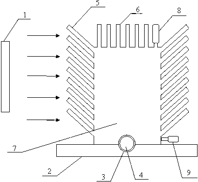
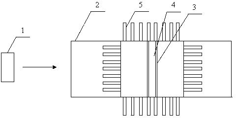
[0022] Such as figure 1 , 2 As shown, the heat dissipation device of this high-power diode-pumped laser includes at least a base 2, a heat dissipation chamber 7 and a fan 1, and its base 2 has a groove 3, and the laser medium is placed in the groove 3; the heat dissipation chamber 7 is Rectangular cavity, the cooling cavity 7 is bonded to the base to form a closed space, antifreeze and laser rod 4 are in the closed space formed by the cooling cavity 7 and the base 2, the top 6 of the cooling cavity has a liquid inlet 8, and the bottom has a liquid outlet Port 9; the fan 1 performs air cooling and heat dissipation on the side of the heat dissipation chamber 7 to the heat dissipation chamber 7.

[0023] The top 6 of the heat dissipation chamber has heat dissipation spines 5, which are perpendicular to the top surface; the side has heat dissipation spines 5 all around, and the heat dissipation spines 5 have an included angle of 45 degrees with the side of the heat dissipation ca...

Embodiment 2

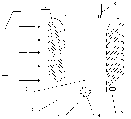
[0027] Such as image 3 , 4 As shown, the structure of this embodiment is basically the same as that of Embodiment 1. The difference is that its heat dissipation chamber 7 adopts an elliptical cylindrical cavity, and the elliptical cylindrical cavity only has heat dissipation thorns 5 around the side. The heat dissipation thorns 5 and the side of the cavity are formed by The included angle is 45 degrees, the top 6 of the cooling chamber is a plane, and there is a liquid inlet 9.

[0028] Such as Figure 6 As shown, in the traditional heat sink clamping heat dissipation method, the heat sink and the laser rod have irregular contact surfaces, which cannot be regarded as an idealized plane, but are actually point-to-point contacts, resulting in low heat dissipation efficiency and uneven heat dissipation, which in turn affects The quality of the laser output beam.

[0029] In the present invention, the laser medium, that is, the laser rod, is completely immersed in the coolant ...


PUM


Abstract

The invention belongs to the technical field of laser, and provides a radiating method for a high-power diode pump laser. The radiating method for the high-power diode pump laser at least comprises a base seat, a radiating cavity and a fan. The radiating method for the high-power diode pump laser is characterized in that a groove is formed in the base seat, and laser medium is placed in the groove; the radiating cavity is a cuboid or cylinder or elliptical cylinder structure without a bottom surface, the radiating cavity is bonded with the base seat to form an enclosed space, the laser medium and cooling liquid are placed in the enclosed space formed by the radiating cavity and the base seat, a liquid inlet is formed in the top of the radiating cavity, and a liquid outlet is formed in the bottom of the radiating cavity; and the fan performs wind cooling radiating for the radiating cavity from one side face of the radiating cavity. Due to the method, the laser medium is completely soaked into the cooling liquid for cooling, the problems that radiating efficiency is low and radiation is uneven are avoided, and a radiating device for the high-power diode pump laser is provided.

Description

technical field [0001] The invention belongs to the technical field of lasers, and relates to a heat dissipation method for a laser, in particular to a heat dissipation method for a high-power diode-pumped laser. Background technique [0002] At present, most of the high-power diode-pumped lasers used in the military and other fields are cooled by water. The traditional water cooling method uses water to dissipate heat from the heat sink that holds the laser medium, and then indirectly dissipates heat to the laser medium. This heat dissipation method is not efficient, and the heat dissipation of the laser medium is not uniform in all directions. The main reason is that due to the actual processing method and the inherent characteristics of the material, the ideal surface-to-surface contact between the laser medium and the heat sink cannot be achieved, in fact, it is a point-to-point contact. Therefore, the traditional water-cooled heat dissipation has the problems of low h...

Claims


Application Information

Patent Timeline
Patent Type & Authority Applications(China)
IPC IPC(8): H01S3/042
Inventor 闫喜龙
Owner XIDIAN UNIV
Why Eureka
Try Eureka