AVC (automatic voltage control) system-based reactive voltage optimization method and device

A voltage optimization and voltage technology, applied in the direction of reactive power compensation, AC network voltage adjustment, etc., can solve the problems of insufficient capacity during peak hours, high network transmission loss, increased operating burden and equipment loss, etc., to achieve large data volume and improve power consumption Utilization, the effect of optimizing voltage stability

Active Publication Date: 2013-06-12
STATE GRID CORP OF CHINA +2
View PDF2 Cites 22 Cited by
  • Summary
  • Abstract
  • Description
  • Claims
  • Application Information

AI Technical Summary

Problems solved by technology

After researching the existing power grid compensation amount, the inventor found that the existing reactive power and voltage optimization methods have the following problems: (1) In the initial stage of substation commissioning, the capacity of a single capacitor is too large, and it cannot be used when it needs to be put into operation, and After a certain number of years of operation, the capacity is too large during the valley period, and the capacity is insufficient during the peak period; (2) There is a lack of appropriate grouping in the operation of the power grid, and frequent switching is required to ensure voltage quality, which increases the operating burden and equipment loss; (3) Capacitor configuration The capacity is large, but the network transmission loss is still high

Method used


Image

  • AVC (automatic voltage control) system-based reactive voltage optimization method and device
  • AVC (automatic voltage control) system-based reactive voltage optimization method and device
  • AVC (automatic voltage control) system-based reactive voltage optimization method and device

Examples


Embodiment Construction

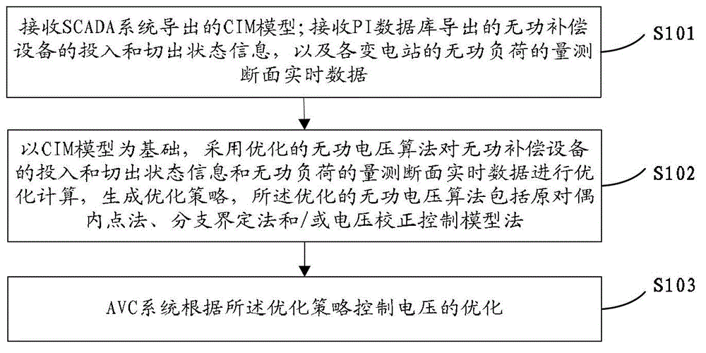
[0037] In order to enable those skilled in the art to better understand the technical solutions in the present application, the technical solutions in the embodiments of the present application will be clearly and completely described below in conjunction with the drawings in the embodiments of the present application. Obviously, the described The embodiments are only some of the embodiments of the present application, but not all of them. Based on the embodiments in this application, all other embodiments obtained by persons of ordinary skill in the art without creative efforts shall fall within the scope of protection of this application.

[0038] Before introducing various embodiments of the application in detail, the individual concepts involved in the application are briefly explained:

[0039] The AVC system (Automatic Voltage Control, automatic voltage control) mentioned in this application means that according to the target conditions and constraints given by the contr...


PUM


Abstract

The embodiment of the application discloses an AVC (Automatic Voltage Control) system-based reactive voltage optimization method. The method comprises the following steps of: receiving a CIM (Common Information Model) which is derived through an SCADA (Supervisory Control And Data Acquisition) system; receiving input and switching out status information of reactive-load compensation equipment which is derived through a PI (Plant Information System), and reactive-load measurement section real-time data of transformer substations; on the basis of the CIM, optimally calculating the input and switching out status information of the reactive-load compensation equipment and the reactive-load measurement section real-time data through an optimized reactive voltage algorithm, and generating an optimized strategy, wherein the optimized reactive voltage algorithm comprises a primary dual interior point method, a branch-and-bound method and/or a voltage correcting control model method; and the AVC system controls optimization of the voltage according to the optimized strategy. The embodiment of the application further discloses an AVC system-based reactive voltage optimization device. Utilization efficiency of electrical energy can be improved through the embodiment of the application.

Description

technical field [0001] The present application relates to the field of electric power technology, in particular to a reactive voltage optimization method and a corresponding device. Background technique [0002] Voltage is an important indicator of power quality, and it has an important impact on the safe and economical operation of the power system and the service life of electrical equipment. The reactive power compensation and reactive power balance of the power system are the basic conditions to ensure the voltage quality. Effective control and reasonable reactive power compensation can not only ensure the voltage quality, but also improve the stability and safety of the power system operation and reduce power loss. . [0003] The reason why the power system needs reactive power compensation is that during the transmission of AC power, if it passes through a purely resistive load, the electric energy will be fully converted into heat energy. If it passes through a "pure...

Claims


Application Information

Patent Timeline
Patent Type & Authority Applications(China)
IPC IPC(8): H02J3/16
CPCY02E40/30
Inventor 李丰伟蔡振华王波龚向阳王威任雷华建良王晴顾伟励文伟王晓罗轶
Owner STATE GRID CORP OF CHINA
Why Eureka
Try Eureka