
Control circuit for ultralow standby power consumption power supply

A technology for standby power consumption and control circuit, applied in the field of microelectronics, can solve the problems of large standby power consumption and reduce standby power consumption of the system, and achieve the effect of reducing standby power consumption and power consumption

Active Publication Date: 2015-02-25
NANJING MICRO ONE ELECTRONICS
View PDF3 Cites 0 Cited by
  • Summary
  • Abstract
  • Description
  • Claims
  • Application Information

AI Technical Summary

Problems solved by technology

[0004] The purpose of the invention is to solve the traditional AC-DC power supply system, due to chip power consumption P ic and chip peripheral components power consumption P s To solve the problem of large standby power consumption of the system, a control circuit of an ultra-low standby power supply is provided. When working, the system output is loaded with P o Converted to the on-chip error amplifier output voltage V ea , then V ea Compared with the internal set voltage V3, when there is an intersection between the two, the circuit will be reversed, and the logic control signal T will be output urn_on / off , so that the chip enters the sleep mode, turns off most of the modules and switch tubes inside the chip, removes the power consumption on the dummy load at the output end, and at the same time adopts high-voltage startup, which saves the power consumption of the startup part, thus greatly reducing the whole machine Standby power consumption

Method used


Image

  • Control circuit for ultralow standby power consumption power supply
  • Control circuit for ultralow standby power consumption power supply
  • Control circuit for ultralow standby power consumption power supply

Examples


Embodiment Construction

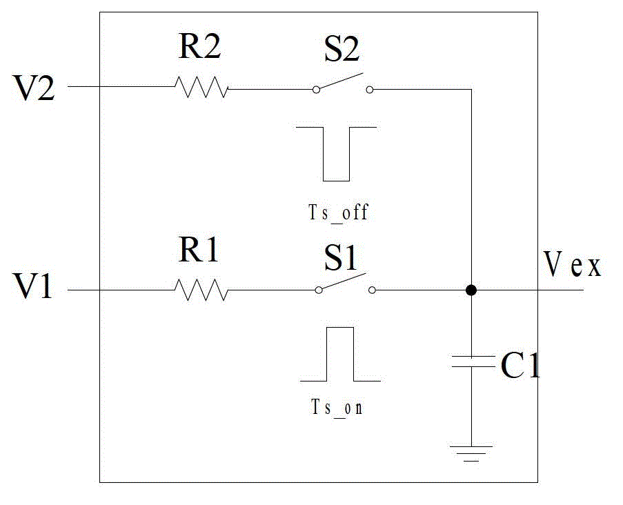
[0019] image 3 For the existing AC-DC primary side control chip internal reference voltage V ex A circuit diagram is generated, which is still used in the present invention.

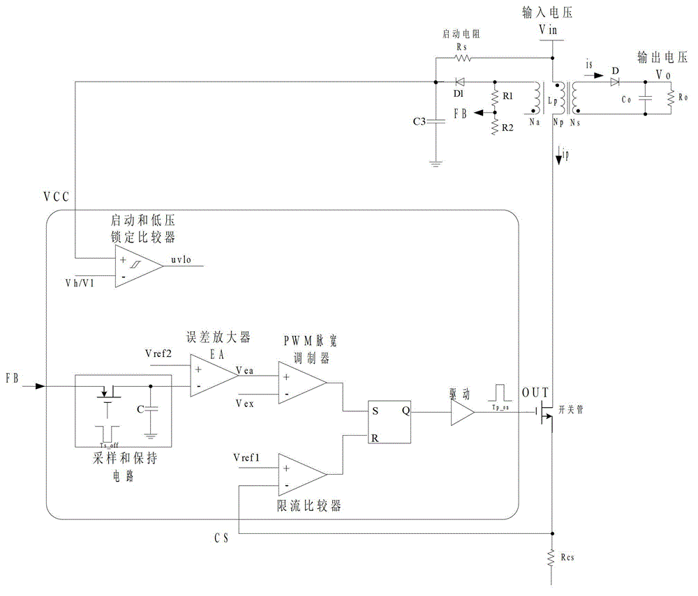
[0020] Such as Figure 5 , Figure 6 , the present invention is based on the existing AC-DC primary side control converter topology, increases the sleep judgment module, and removes the external start-up circuit ( figure 2 The starting resistor R in S ). The sleep judgment module includes a high-voltage startup Jfet tube, a sleep judgment comparator and an RS flip-flop. External input voltage V in The primary inductance of the transformer is connected to the high-voltage drain terminal Drain of the Jfet tube, the low-voltage source terminal of the Jfet is connected to the chip power supply terminal VCC, the gate of the Jfet is connected to the uvlo signal, and the initial state of the Jfet is a conduction state. The set voltage V3 is connected to one end of the sleep judgment comparator, and the...


PUM


Abstract

The invention discloses a control circuit for an ultralow standby power consumption power supply. On the basis of the structure of an alternating current-direct current (AC-DC) primary-side-control converter, an outside starting circuit is eliminated, and a sleep judgment module is additionally arranged. The sleep judgment module comprises a high-voltage starting junction field-effect transistor (Jfet) tube, a sleep judgment comparator and an RS trigger; an outside power supply is connected with the drain of the Jfet tube through a primary inductor of a transformer; a chip power supply is connected with the source of the Jfet tube; the grid of the Jfet tube is connected with output signals of a starting and low-voltage locking protection circuit; the positive input end of the sleep judgment comparator is connected with set voltage, and the negative input end is connected with output signals of an error amplifier; output signals of the sleep judgment comparator are connected with the R end of the RS trigger; output signals of a low-voltage locking protection comparator are connected with the S end of the RS trigger; and the RS trigger outputs a sleep or starting control signal to control and enable most circuits of a chip and a switch tube in a peripheral circuit, so that the chip enters a sleep mode, and the standby power consumption of the system is reduced.

Description

technical field [0001] The invention relates to a switching power supply, in particular to a control circuit of an ultra-low standby power supply, and belongs to the technical field of microelectronics. Background technique [0002] For a switching power supply circuit, not only high conversion efficiency is required, but also low standby power consumption is required. At present, in terms of reducing standby power consumption, whether it is pulse frequency modulation (PFM), pulse width modulation (PWM) or hybrid control methods, it is achieved by reducing the frequency of the power control chip and reducing the power consumption of the control circuit. Low standby power consumption. As far as the existing power control chip reduces the standby power consumption, there is little room for reducing the power consumption of the control circuit, and the standby power consumption cannot be further reduced. [0003] AC-DC primary side control (PSR) converter has become the devel...

Claims


Application Information

Patent Timeline
Patent Type & Authority Patents(China)
IPC IPC(8): H02M3/335
CPCY02B70/16Y02B70/10
Inventor 张洪俞朱敏元鲁华夏晓娟
Owner NANJING MICRO ONE ELECTRONICS
Features
  • Generate Ideas
  • Intellectual Property
  • Life Sciences
  • Materials
  • Tech Scout
  • Unparalleled Data Quality
  • Higher Quality Content
  • 60% Fewer Hallucinations
Learn More