Method of electrospinning fibres

A technology of fiber and electrical conductivity, which is applied in the field of controlling the texture and structure of fibers and vesicles, and can solve problems such as curling, unstable liquid jet, and non-straight fibers

Inactive Publication Date: 2013-06-12
科学技术设备委员会
View PDF2 Cites 12 Cited by
  • Summary
  • Abstract
  • Description
  • Claims
  • Application Information

AI Technical Summary

Problems solved by technology

Instability of the liquid jet and evaporation of the solvent can cause the fiber to be misaligned and possibly curled

Method used


Image

  • Method of electrospinning fibres
  • Method of electrospinning fibres
  • Method of electrospinning fibres

Examples


Embodiment Construction

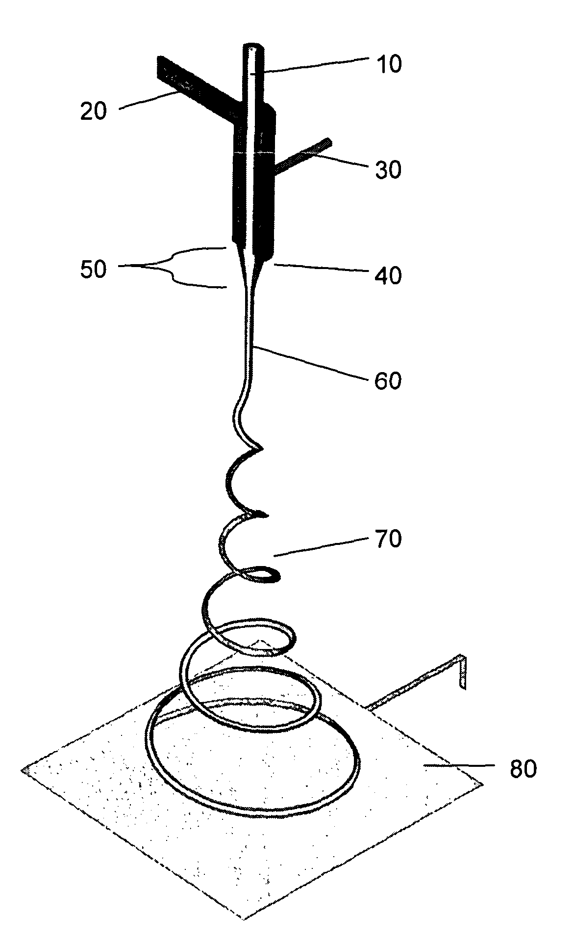
[0077] Figure 4 is a flow chart showing the steps of making fibers according to the present invention. The manufactured fiber has a core of a first material and a sheath surrounding the core of a second material different from the first material. image 3 Shown is the equipment and layout used for the method.

[0078] The device includes a reservoir (not shown) fluidly connected to the nozzle 40 . The nozzle includes an inner core channel and an outer concentric annular channel which receive fluid from the reservoir. The openings in the nozzle are a central circular opening corresponding to the core and an annular concentric opening corresponding to the shell. Other shapes and arrangements of openings are possible, eg a series of openings arranged in a circle for the shell fluid. As the fluid flows through the multiple shell openings, the fluids combine to form a shell surrounding the core.

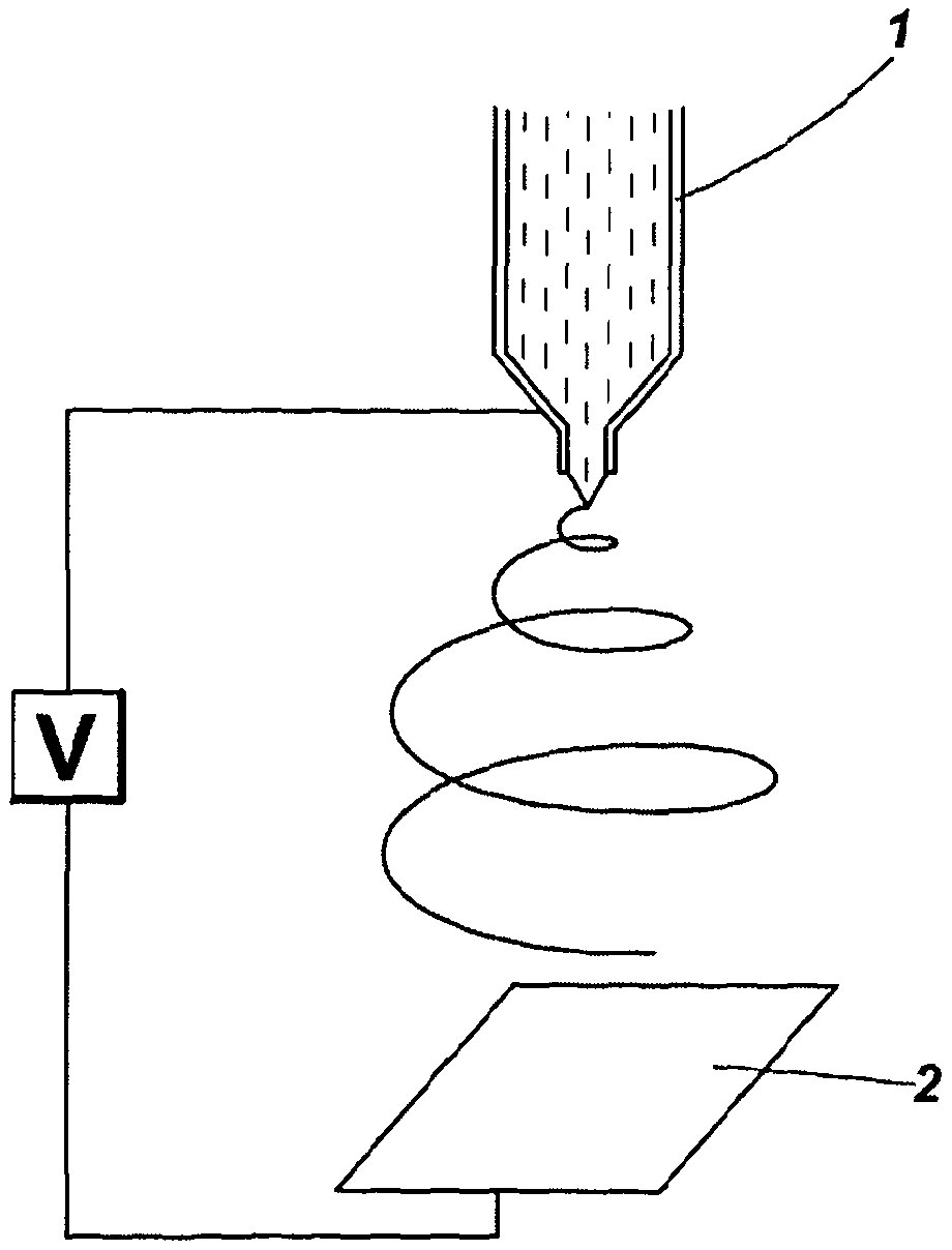
[0079] Spaced from the nozzle is a collector 80 . It can be a conductive plate...


PUM

PropertyMeasurementUnit
electrical conductivityaaaaaaaaaa
diameteraaaaaaaaaa
diameteraaaaaaaaaa

Abstract

A method of electrospinning fibres is disclosed. The fibres have an inner core surrounded by a porous outer shell. The method comprises co-electrospinning first and second liquids as core and shell respectively, the second liquid surrounding the first liquid in a jet issuing from a Taylor cone, wherein the first and second liquids are miscible or semi-miscible with each other, such that pore generation is driven in the shell of the fibre. The liquids may be solutions or melts. The electrical conductivity, viscosity, miscibility and other parameters of the liquids determine the structure of the produced fibres. As well as producing fibres having a porous shell there are described methods of co-electrospraying porous beads as well as core- shell vesicles having a porous shell. The methods may be used to produce hydrogen storage fibres, vesicles and beads.; The methods may also be used for producing controlled drug- delivery fibres, vesicles and beads.

Description

technical field [0001] The present invention relates to a method of electrospinning fibers having an inner core surrounded by a sheath. The invention also relates to a method of producing solid or fluid filled vesicles using electrospray. In particular, the invention relates to methods of controlling the texture and structure of fibers and vesicles. Background technique [0002] Electrospraying is a technique for dispersing liquids to create aerosols. In this technique, liquid is fed through a capillary and a high voltage is applied to the tip of the capillary. Also provided is a plate biased with a low voltage (eg, ground) spaced apart from the capillary in a direction normal to the capillary. The higher potential at the tip induces the formation of Taylor cones. A jet of liquid is ejected through the tip of the cone. Such as figure 1 As shown, the jet rapidly forms droplets due to Coulomb repulsion in the jet. [0003] figure 2 Shown is the related technique of el...

Claims


Application Information

Patent Timeline
Patent Type & Authority Applications(China)
IPC IPC(8): D01F8/00D01D5/00B82Y30/00D01D5/24A61L27/56H01M8/04
CPCA61L15/44A61L27/54A61L2300/626C01B3/001C01B3/0026C01B3/0031C01B3/0078C01B3/0084D01D5/0015D01D5/247D01F8/00H01M8/04216Y02E60/32Y02E60/50A61L15/22A61L15/425A61L27/44A61L27/56B05D1/06D01D5/0007D01D5/34D01D5/00D01D5/24D01D5/0038
Inventor W·I·F·大卫M·欧文-琼斯D·W·K·詹金斯S·本宁顿A·洛弗尔Z·库尔班
Owner 科学技术设备委员会
Why Eureka
Try Eureka