Cable path electriferous probing method and device

A detection method and detection device technology, applied in the direction of measuring devices, electric/magnetic exploration, radio wave measurement systems, etc., can solve the problems of large environmental differences, low attention, incompleteness, etc., and achieve weak power frequency interference, Good detection accuracy and improved efficiency

Inactive Publication Date: 2013-06-19
上海铁新地理信息有限公司 +2
View PDF8 Cites 9 Cited by
  • Summary
  • Abstract
  • Description
  • Claims
  • Application Information

AI Technical Summary

Problems solved by technology

It happens from time to time to find the wrong cable according to the existing label of the equipment, especially the inaccurate ratio of the equipment label of the same bus double cable is relatively high
[0004] 2. The missing ratio of cable equipment routing diagram is high
[0005] 3. The missing ratio of cable equipment connector location map is high
Due to the low degree of attention paid to low-voltage cable equipment in the past, the management requirements of the operating unit for the as-built drawings of low-voltage cables and the location drawings of cable joints are not strict, resulting in a factual lack, which constitutes a great obstacle to the cable route survey and cable fault location.
[0006] Due to inaccurate, incomplete, incomplete, discrete, diverse formats, and inconsistent data standards of underground pipeline archives, it is difficult to use information, low in sharing, and even cause engineering accidents to occur from time to time. How to improve the quality monitoring and assurance of underground pipeline information results mechanism is one of the outstanding issues that need to be resolved as soon as possible
In the general survey and detection of existing underground pipelines, the accuracy and efficiency of detection need to be improved due to factors such as complex geological conditions, large environmental differences, extensive use of non-metallic pipes, and the gradual increase of non-excavation deep buried pipelines.

Method used


Image

  • Cable path electriferous probing method and device
  • Cable path electriferous probing method and device
  • Cable path electriferous probing method and device

Examples


Embodiment

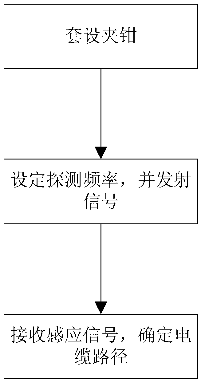
[0026] Such as figure 1 As shown, a cable path live detection method, the specific steps of the method for detecting 380V low-voltage cables include:

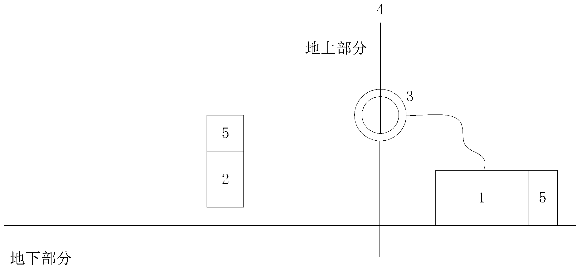
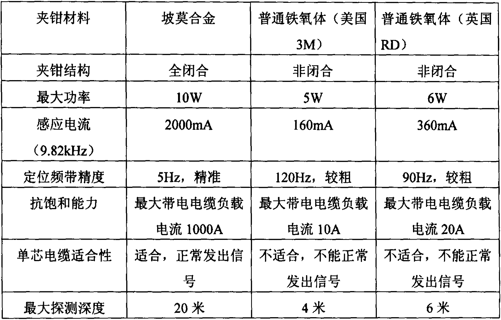
[0027] Step 1, set the clamp on the ground part of the cable to be tested. Here, the clamp adopts a closed annular permalloy clamp, which can be operated live, and because permalloy has a high magnetic permeability of weak magnetic field, and adopts a fully closed ring structure, it can well detect The signal is induced to the formation where the underground part of the cable to be tested is located, so that the receiver can better receive the secondary magnetic field signal of the induced current in the cable to be tested. Compared with ordinary clamps, its performance has obvious advantages, as shown in Table 1.

[0028] Table 1

[0029]

[0030] Step 2: The transmitter transmits the detection signal, and the detection signal is induced to the stratum where the underground part of the cable to be tested is located throu...


PUM


Abstract

The invention relates to a cable path electriferous probing method and device. The method comprises the following steps: sleeving an overground part of a cable to be tested; a transmitter transmits probing signals and senses probing signals to the ground layers which the underground part of the cable to be tested locates in through the clamp; and a receiver receives secondary magnet field signals of sensing target in the cable to be tested and confirms cable path according to intensity of the secondary magnet field signals. The device comprises a sending machine, a receiving machine and a permalloy clamp, the permalloy clamp is a closed type annular clamp and is sleeved on the overground part of the cable to be tested, and a signal input end of the permalloy clamp is connected with a sending machine. Compared with the prior art, the cable path electriferous probing method and device have the advantages of being good in probing accuracy, high in efficiency and the like.

Description

technical field [0001] The invention relates to a cable path detection technology, in particular to a complex path charged detection method and device suitable for low-voltage cables. Background technique [0002] Low-voltage power cables are the lowest rated voltage cable equipment of the State Grid Corporation of China. At present, most low-voltage power cables are at the nerve endings of the power grid, and the level of equipment management is far behind the standardized management of high-voltage power cables. Specifically in the following aspects: [0003] 1. There is a high proportion of inconsistency between the near-end cable terminal and the far-end terminal of the equipment. It happens from time to time to find the wrong cable according to the existing nameplate of the equipment, especially the inaccurate ratio of the equipment nameplate of the same bus double cable is relatively high. [0004] 2. The missing ratio of cable equipment routing diagram is high. Du...

Claims


Application Information

Patent Timeline
Patent Type & Authority Applications(China)
IPC IPC(8): G01V3/08
Inventor 崔浩葛忠梁卢燕陆遥严倩倩陈晓峰
Owner 上海铁新地理信息有限公司
Why Eureka
Try Eureka