
Locating jig

A positioning jig and positioning hole technology, applied in nonlinear optics, instruments, optics, etc., can solve the problems of reducing the production yield of finished products, poor positioning, damage to the protective film and frame, etc., and achieve the effect of improving efficiency and accuracy.

Inactive Publication Date: 2013-06-19
INVENTEC CORP
View PDF0 Cites 5 Cited by
  • Summary
  • Abstract
  • Description
  • Claims
  • Application Information

AI Technical Summary

Problems solved by technology

However, the material of the frame is relatively soft, and it is easy to bend and deform if it is positioned by vacuum adsorption
Moreover, positioning and attaching the protective film by manual visual inspection is easy to cause poor positioning and must be disassembled and repositioned, thus causing damage to the protective film and frame, reducing the production yield of the finished product, and costing more of manual adjustment time, which cannot effectively improve work efficiency

Method used


Image

  • Locating jig
  • Locating jig
  • Locating jig

Examples


Embodiment Construction

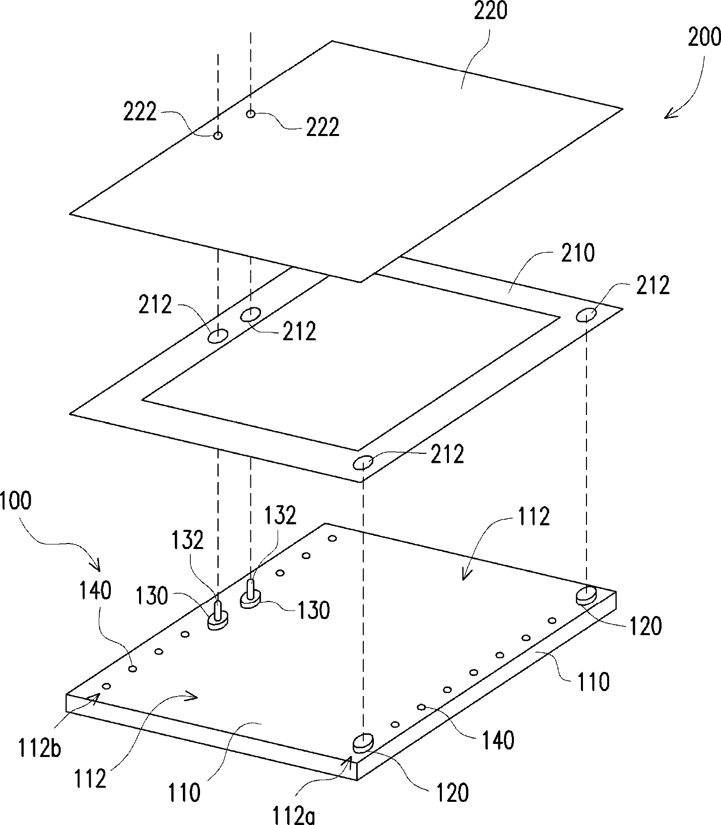
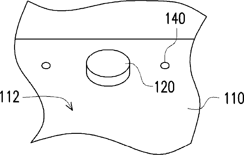
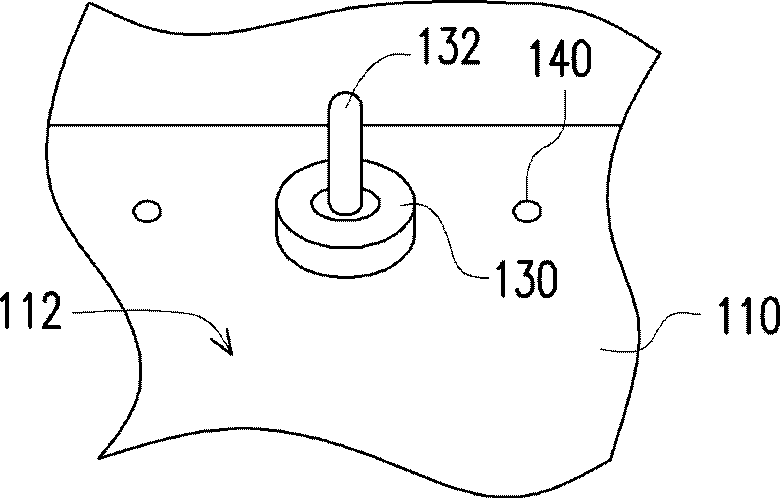
[0035] figure 1 It is an exploded schematic diagram of a positioning jig, a frame and a protective film according to an embodiment of the present invention. Please refer to figure 1 , the present invention proposes a positioning jig 100 suitable for positioning between a frame 210 and a protective film 220 of a flat panel display 200 . Wherein, the frame 210 has a plurality of first positioning holes 212 (four are shown), and the protective film 220 has a plurality of second positioning holes 222 (two are shown). The material of the protective film can be transparent materials such as acrylic and glass, and the material of the frame can be rubber. The flat panel display 200 can be a liquid crystal display, a plasma display, or an organic light emitting diode display. In this embodiment, the flat panel display 200 is a liquid crystal display. The positioning jig 100 includes a platform 110 , a plurality of first positioning seats 120 (two are shown), and a plurality of seco...


PUM


Abstract

Provided is a locating jig. The locating jig is suitable for the location of a frame and a protective film of a two-dimensional display. The frame is provided with a plurality of first locating holes, and the protective film is provided with a plurality of second locating holes. The locating jig comprises a platform, a plurality of first locating seats and a plurality of second locating seats. The platform is provided with an upper surface which is suitable for bearing the frame. The first locating seats are suitable for being connected with part of first locating holes in an embedding mode. Each second locating seat is provided with a locating column, the second locating seats are suitable for being connected with the other part of first locating holes in an embedding mode, and the locating columns are suitable for being respectively connected with the second locating holes in an embedding mode.

Description

technical field [0001] The invention relates to a jig, in particular to a positioning jig. Background technique [0002] Liquid crystal displays have the advantages of high image quality, small size, light weight, low voltage drive, low power consumption, and wide application range. They have been widely used in medium and small portable TVs, mobile phones, video recorders, notebooks, etc. Consumer electronics or computer products such as desktop computers, desktop monitors, and projection televisions have gradually replaced cathode ray tubes (Cathode Ray Tube, CRT) as the mainstream of displays. [0003] The existing method of positioning and attaching the protective film of the liquid crystal display to its frame mostly uses vacuum adsorption to position the frame, and then positions and attaches the protective film by manual visual inspection. However, the material of the frame is relatively soft, and it is easy to bend and deform if it is positioned by vacuum adsorption...

Claims


Application Information

Patent Timeline
IPC IPC(8): G02F1/13
Inventor 黄韦智
Owner INVENTEC CORP
Learn More