Vacuum contactor for wind power generation

A technology of vacuum contactor and vacuum switch tube, which is applied in the direction of high-voltage air circuit breakers, circuits, electric switches, etc., and can solve the problems that cannot meet the needs of wind power generation, high current, high stability and reliability, and it is difficult to realize synchronous closing or opening, Unable to use high-power power generation equipment and other problems

Inactive Publication Date: 2013-06-19
无锡市蓝虹电子有限公司
View PDF6 Cites 0 Cited by
  • Summary
  • Abstract
  • Description
  • Claims
  • Application Information

AI Technical Summary

Problems solved by technology

Due to the use of a vacuum switching tube, its rated operating current is only less than 2000 amperes, so that this vacuum contactor can only be used on small and medium power electric equipment, and cannot be used on high-power power generation equipment, especially wind power generation above 3000 amperes It cannot be used on board at all, and the scope of application is limited
On the other hand, since one end of the crank arm is directly connected with the lower end of the movable co...

Method used


Image

  • Vacuum contactor for wind power generation
  • Vacuum contactor for wind power generation
  • Vacuum contactor for wind power generation

Examples


Embodiment Construction

[0019] The present invention is described in further detail below in conjunction with embodiment.

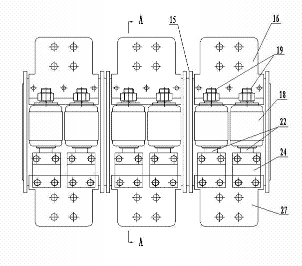
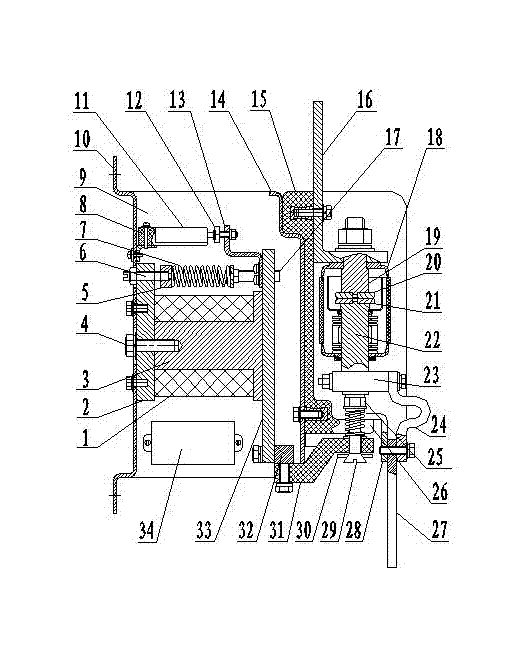
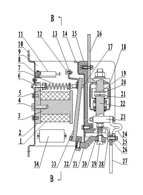
[0020] Such as figure 1 and figure 2 As shown, the vacuum contactor for wind power generation of the present invention includes a rear base plate 10 and a front base plate 14, the front base plate 14 and the rear base plate 10 are both iron plates, and the same vertical sides of the front base plate 14 and the rear base plate 10 pass through the side The plates 9 are connected together with fasteners, wherein the fasteners consist of bolts and nuts. Four static armature plates 2 are arranged in the middle of the inner surface of the rear base plate 10 , and the static armature plates 2 are fixed on the inner surface of the rear base plate 10 by means of screws. A static iron core 3 is arranged on the inner side of the static armature plate 2 , and the static iron core is fixed together with the static armature plate 2 by means of bolts 4 . The coil 1 is wound on the static i...


PUM


Abstract

The invention discloses a vacuum contactor for wind power generation. The vacuum contactor comprises a rear substrate and a front substrate. An auxiliary switch, a static armature plate and a secondary power module are fixed on the inner side face of the rear substrate. A static iron core and a coil which are configured according to a proportion of 1:1 among vacuum switch tubes, the static iron core and the coil are mounted on the static armature plate. A moving armature plate is located between the static armature plate and the front substrate, a separating brake spring is located between the moving armature plate and the static armature plate, a plate playing screw is arranged in the inner side of the upper edge of the moving armature plate, and one end of the auxiliary switch is provided with a contact. A static coil out row and a moving coil out row are respectively fixed on the upper edge and the lower edge of the outer surface of the front substrate. The vacuum switch tubes are arranged between the static coil out row and the moving coil out row, and static conducting rods and moving conducting rods of the vacuum switch tubes are respectively connected with the static coil out row and the moving coil out row. A rotating shaft is arranged below the moving armature plate. A crank arm is arranged between the rotating shaft and the moving conducting rods in a connection mode. Two vacuum switch tubes are in parallel connection with each electrode between the static coil out row and the moving coil out row. The vacuum contactor is not only large in working currents and wide in application range, but also stable in switching in performance and good in quality, and especially suitable for being used on wind driven generators.

Description

technical field [0001] The invention relates to an electrical switch. Specifically, it is a high-current vacuum contactor used to transmit the electricity generated by the wind turbine to the grid. Background technique [0002] It is known in the field of electric appliance manufacturing that traditional vacuum contactors use a vacuum switching tube. Due to the use of a vacuum switching tube, its rated operating current is only less than 2000 amperes, so that this vacuum contactor can only be used on small and medium power electric equipment, and cannot be used on high-power power generation equipment, especially wind power generation above 3000 amperes It cannot be used on board at all, and the scope of application is limited. In traditional vacuum contactors, the number of static iron cores and coils is small. Usually, the vacuum switch tube, static iron core and coils are arranged according to the ratio of vacuum switch tube: static iron core and coil = 1.5:1. The suct...

Claims


Application Information

Patent Timeline
IPC IPC(8): H01H33/66
Inventor 沈兴元张志忠
Owner 无锡市蓝虹电子有限公司
Why Eureka
Try Eureka