Microstrip line slow-wave structure
A technology of slow wave structure and microstrip line, which is applied in the circuit components of transit time type electron tubes, etc., can solve the problems of large working voltage, limited application development, and large working voltage.
- Summary
- Abstract
- Description
- Claims
- Application Information
AI Technical Summary
Problems solved by technology
Method used
Image
Examples
Embodiment Construction
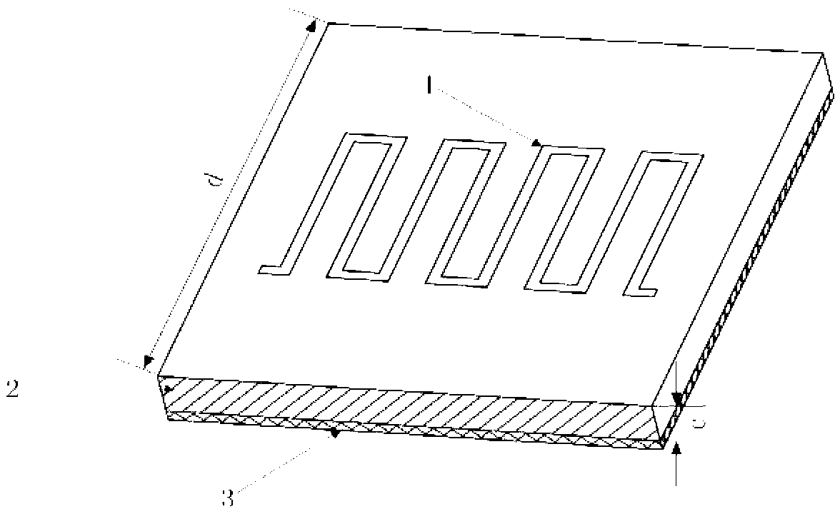
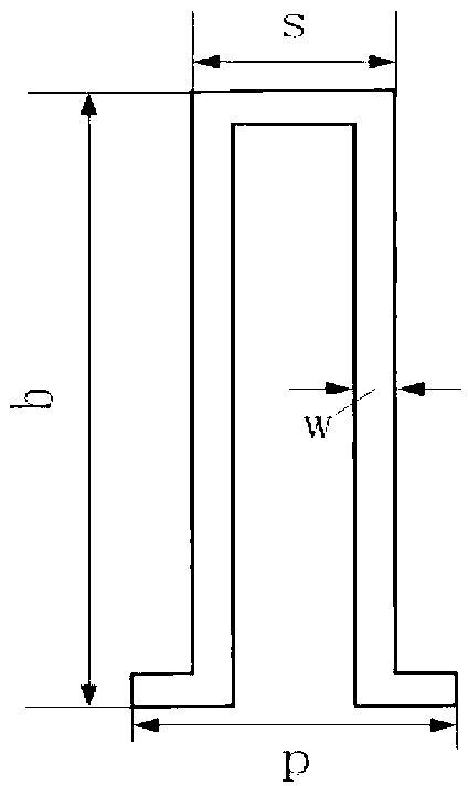
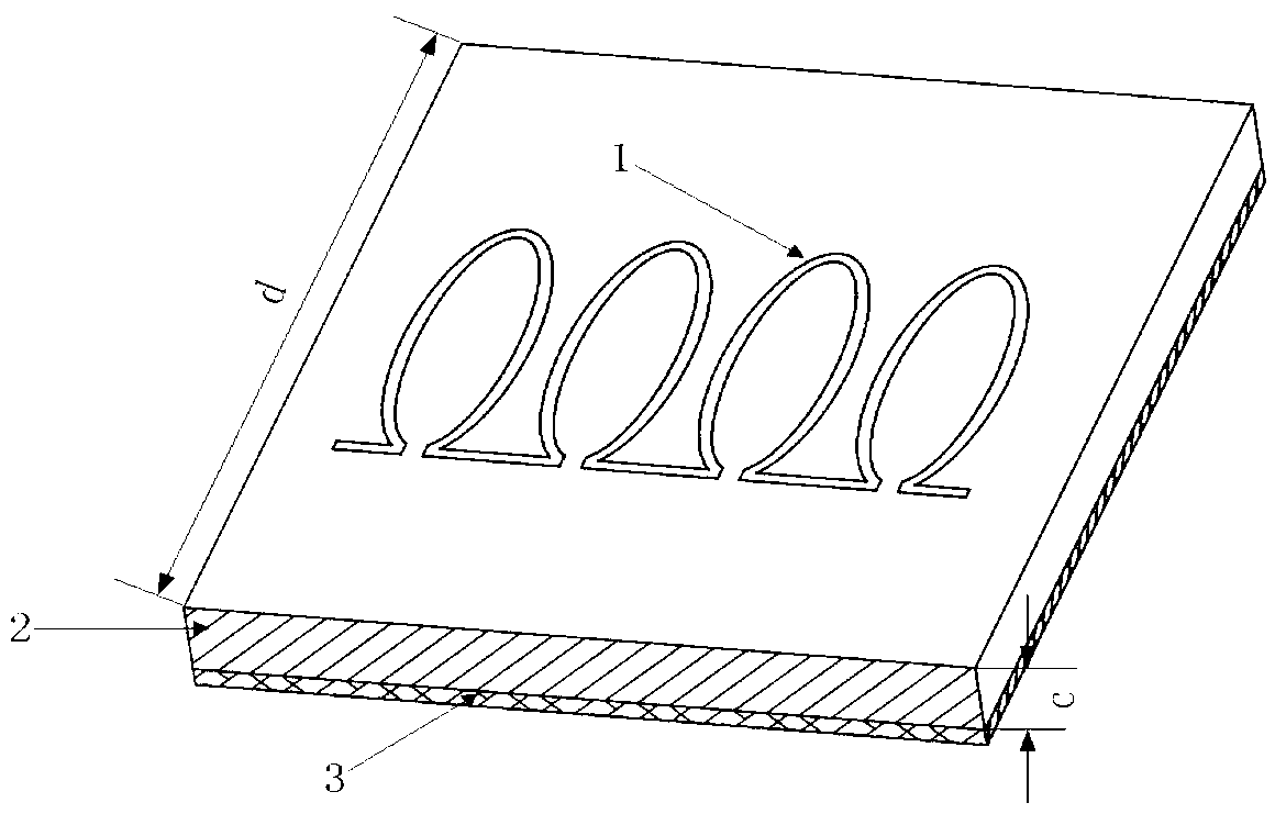
[0017] A kind of microstrip zigzag line slow wave structure, such as image 3 , 4 As shown, it includes a microstrip transmission line structure formed by a metal microstrip line 1, a dielectric substrate 2 and a metal bottom plate 3; the metal microstrip line 1 is located on the front of the dielectric substrate 2, and the metal bottom plate 3 is close to the back of the dielectric substrate 2. The metal microstrip line 1 is composed of a number of "O"-shaped metal microstrip line units connected end to end to form a periodic structure, wherein the "O"-shaped metal microstrip line unit consists of an elliptical open ring microstrip line and two sections respectively. It is composed of a microstrip line connected to both ends of the opening of the oval split ring microstrip line.
[0018] Define the size parameters of the aforementioned microstrip line slow-wave structure: a is the length of the horizontal axis of the elliptical split ring, b is the length of the longitudinal axis...
PUM
 Abstract
Description
Claims
Application Information
 - R&D
- Intellectual Property
- Life Sciences
- Materials
- Tech Scout
- Unparalleled Data Quality
- Higher Quality Content
- 60% Fewer Hallucinations
Browse by: Latest US Patents, China's latest patents, Technical Efficacy Thesaurus, Application Domain, Technology Topic, Popular Technical Reports.
© 2025 PatSnap. All rights reserved.Legal|Privacy policy|Modern Slavery Act Transparency Statement|Sitemap|About US| Contact US: help@patsnap.com


