Motor cabin with variable frequency resonant cavity

A technology of frequency resonance and motor compartment, which is applied in the field of vacuum cleaner motors with noise reduction structure, to achieve reasonable utilization, small occupied space and increased sound energy loss

Inactive Publication Date: 2013-06-26
NANJING LG PANDA APPLIANCES
View PDF5 Cites 3 Cited by
  • Summary
  • Abstract
  • Description
  • Claims
  • Application Information

AI Technical Summary

Problems solved by technology

[0005] At present, there is no motor compartment that can eliminate single-frequency noise through the resonance principle according to different working states of the motor. figure 1

Method used


Image

  • Motor cabin with variable frequency resonant cavity
  • Motor cabin with variable frequency resonant cavity
  • Motor cabin with variable frequency resonant cavity

Examples


Embodiment Construction

[0029] The present invention will be further described in detail below in combination with specific embodiments.

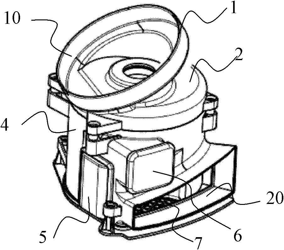
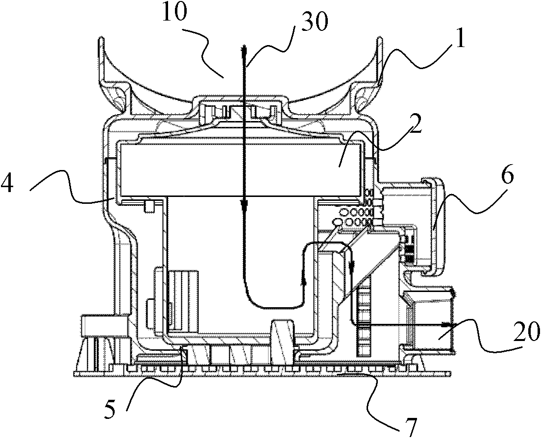
[0030] Such as figure 2 with Figure 4 As shown, the present invention has a motor compartment with a variable frequency resonant cavity, including a motor cover 1, a motor assembly 2, a vibration-isolation rubber pad 3, a motor case 4, a partition type muffler 5 and a lower bottom plate 8, and the motor The top of the cover 1 is provided with a suction port 10 , and an exhaust cavity 20 is formed outside the exhaust filter 5 .

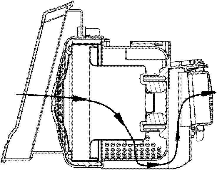
[0031] On the motor casing 4, a variable frequency resonant cavity 6 is formed by a cavity protruding to the outside of the motor casing at the top of the exhaust cavity 20, such as figure 2 with image 3 As shown, the outer wall of the variable frequency resonant cavity 6 is a soft end, that is, a soft backplane is used as the end of the resonant cavity, as Figure 4 shown.

[0032] Image 6 The working principle of the variable ...


PUM


Abstract

The invention discloses a motor cabin with a variable frequency resonant cavity. The motor cabin with the variable frequency resonant cavity comprises a motor cover, a motor assembly, a motor housing, a clapboard-type silencer and a lower portion base plate. A suction inlet is formed in the top of the motor cover, an exhaust cavity is formed in the outer side of an exhaust gas filter, the variable frequency resonant cavity which is formed by a cavity protruded from the motor cover is formed in the motor cover which is arranged above the exhaust cavity, and the outer wall of the variable frequency resonant cavity is a soft tail end. The clapboard-type silencer is arranged at the intersection position of the outer wall of the motor housing located below the variable frequency resonant cavity and the exhaust cavity, and a plurality of clapboards arranged from top to bottom form a plurality of L-shaped sound eliminating cavities in the clapboard-type silencer. Due to the fact that the soft tail end can move as change of pressure difference of inner pressure and outer pressure, the motor cabin with the variable frequency resonant cavity can eliminate sound aiming at different working conditions.

Description

technical field [0001] The invention relates to a vacuum cleaner motor, in particular to a vacuum cleaner motor with a noise reduction structure. Background technique [0002] Generally speaking, a vacuum cleaner is a device that generates suction through a fan motor installed inside the body, and uses the above suction to suck in dust. A vacuum cleaner is an electrical appliance that cleans dust on the ground or carpets through the above-mentioned process. The vacuum cleaner motor is the heart of the vacuum cleaner. The main types of vacuum cleaner motors are: dry vacuum cleaner motor, wet and dry vacuum cleaner motor. The vacuum cleaner motor is composed of two parts: the motor part and the fan part. Since the vacuum cleaner motor has high requirements on the speed, generally at 20,000-30,000 rpm, the motor is mainly a series-excited motor, also known as a series-excited motor. The series-wound motor is a series-connected stator excitation winding and armature (rotor) wi...

Claims


Application Information

Patent Timeline
IPC IPC(8): A47L9/00F01N13/02F01N1/00F01N1/02
Inventor 武甜甜
Owner NANJING LG PANDA APPLIANCES
Why Eureka
Try Eureka