
Double-layer-flow purification working table

A workbench, double-layer flow technology, applied in workbenches, manufacturing tools, clean rooms, etc., can solve the problems of chaotic airflow in the working chamber and rapid discharge of unfavorable volatile substances, and achieve the effect of avoiding airflow reflection.

Inactive Publication Date: 2013-06-26
NANTONG UNIVERSITY
View PDF6 Cites 13 Cited by
  • Summary
  • Abstract
  • Description
  • Claims
  • Application Information

AI Technical Summary

Problems solved by technology

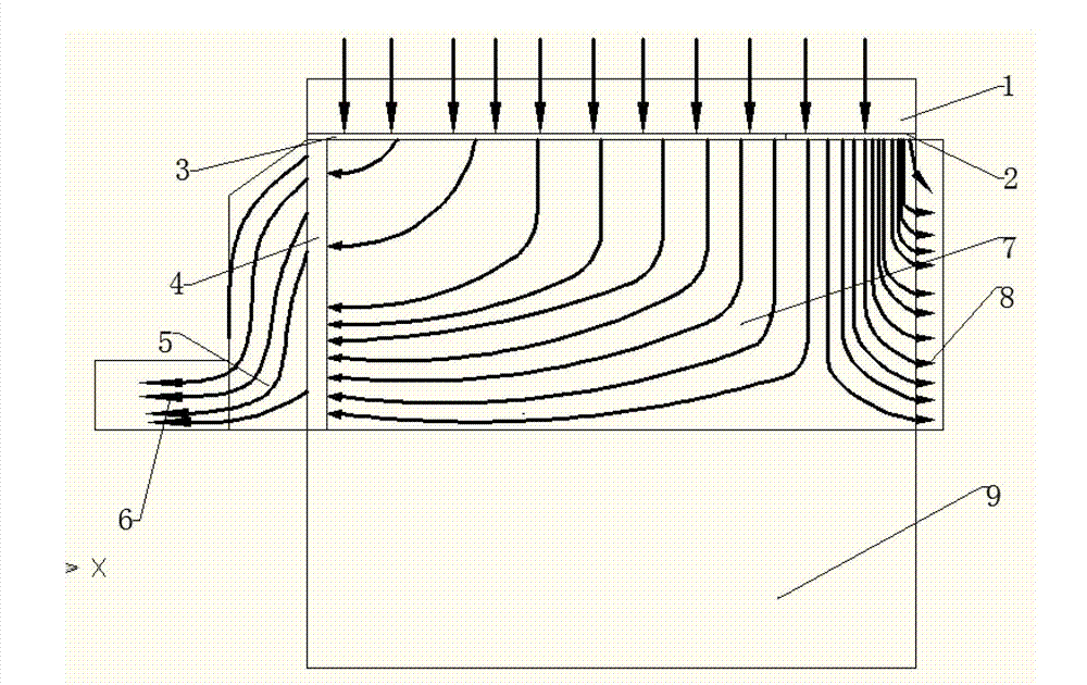
[0004] Existing workbench exhaust systems all extract air from the bottom of the low positive pressure area, and the airflow passing through the diffuser plate often hits the bottom surface of the working chamber and then rebounds (airflow rebound phenomenon), resulting in relatively low airflow inside the working chamber. Confusion, not conducive to rapid discharge of volatile substances

Method used


Image

  • Double-layer-flow purification working table
  • Double-layer-flow purification working table
  • Double-layer-flow purification working table

Examples


Embodiment Construction

[0022] The present invention will be further described below in conjunction with the accompanying drawings and specific embodiments.

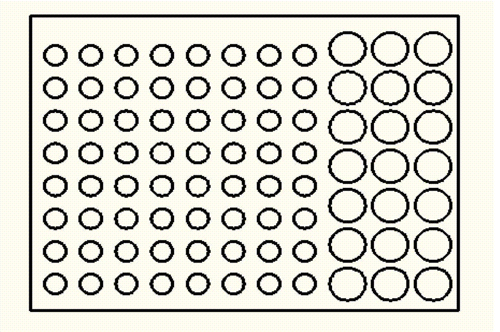
[0023] Such as figure 1 As shown, the double-layer flow purification workbench of the embodiment of the present invention includes an air intake system 1 and an exhaust system. A diffuser plate 3 is provided below the air intake system 1, and a working cavity 7 is located below the diffuser plate 3. The working cavity 7. The outer side is the glass sliding door 8, and the lower part of the working chamber 7 is the bracket 9. The side of the diffuser 3 close to the staff is provided with a large hole in the horizontal direction. The diameter of the large hole is 20mm. , the aperture of the small hole is 10mm, the exhaust system includes a collector plate 4 positioned in the working cavity 7 and placed vertically, the collector plate 4 is located on the side away from the staff in the working cavity 7, the collector plate 4 The opening gradually...


PUM


Abstract

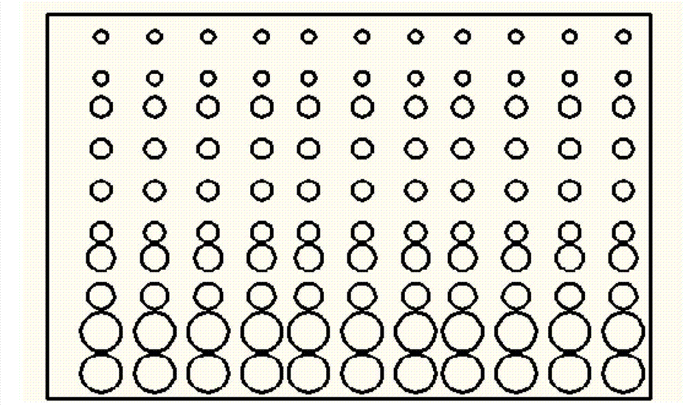
The invention relates to a double-layer-flow purification working table which comprises an air intake system and an air discharging system, wherein an air diffusion plate is arranged below the air intake system; a working chamber is arranged below the air diffusion plate; large holes are formed along the transverse direction on the front side of the air diffusion plate; small holes are formed along the transverse direction at other parts of the air diffusion plate; the air discharging system comprises an air collecting plate which is positioned inside the working chamber and is vertically arranged; the holes in the air collecting plate are increased gradually from top to bottom; an air collecting hood is installed on the outer side of the air collecting plate; the lower part of the air collecting hood is connected with an air discharging device through an air discharging tube; the air flow inside the working chamber is collected by the air collecting hood after horizontally passing through the air collecting plate and is discharged out by the air discharging device through the air discharging tube. By adopting a mutation hole mode, two positive pressure areas are formed at the working chamber, wherein the air pressure on one side close to working personnel is greater than the air pressure on the inner side; the air discharging system is put on the inner side of the working chamber; and by adopting a gradual change hole mode, the air flow inside the working chamber is collected by the air collecting hood after horizontally passing through the air connecting plate, and the phenomenon that the air flow rebounds below the working chamber is avoided.

Description

technical field [0001] The invention relates to a purification workbench, in particular to a double-layer flow purification workbench. Background technique [0002] In industrial production and scientific research, dust-free working environment is required in many places. The purification workbench can provide an effective working environment for these purposes and improve the efficiency of production and scientific research. However, there are some defects in the currently used workbench. Generally speaking, the clean workbench area maintains a positive pressure on the atmosphere, so that there are volatile substances in the work process that will be directly discharged to the body of the operator. This seriously affects the health of the operating personnel. At the same time, during the operation, when the hands and other parts of the operator enter the clean work area, a large amount of dust particles will also be brought in, which will affect the cleanliness of the cle...

Claims


Application Information

Patent Timeline
Patent Type & Authority Applications(China)
IPC IPC(8): B01L1/04B25H1/00
Inventor 花国然王强苏波泳张昱邓洁
Owner NANTONG UNIVERSITY
Learn More