Locomotive traction motor axle suspension bush machining device

A technology for traction motors and processing devices, which is applied to positioning devices, metal processing equipment, metal processing machinery parts, etc., can solve problems affecting the working performance of the inner surface of the bearing pad Babbitt alloy, hidden dangers of driving, and poor lubrication, etc., to achieve improvement Work reliability, safe and reliable operation, and the effect of improving processing efficiency

Inactive Publication Date: 2013-06-26
襄阳中车电机技术有限公司
View PDF7 Cites 3 Cited by
  • Summary
  • Abstract
  • Description
  • Claims
  • Application Information

AI Technical Summary

Problems solved by technology

Because the bearing capacity of the bearing pad of the locomotive motor is large, the working environment is harsh, and the lubrication is poor during the start-up process, the contact accuracy between the Babbitt alloy layer of the bearing pad and the locomotive wheel axle is extremely critical, and the matching accuracy between the outer circle of the bearing pad and the box is critical The shape

Method used


Image

  • Locomotive traction motor axle suspension bush machining device
  • Locomotive traction motor axle suspension bush machining device
  • Locomotive traction motor axle suspension bush machining device

Examples


Embodiment Construction

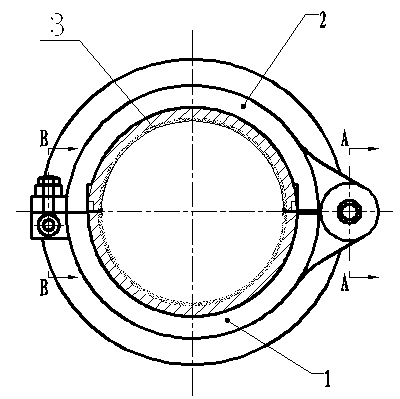
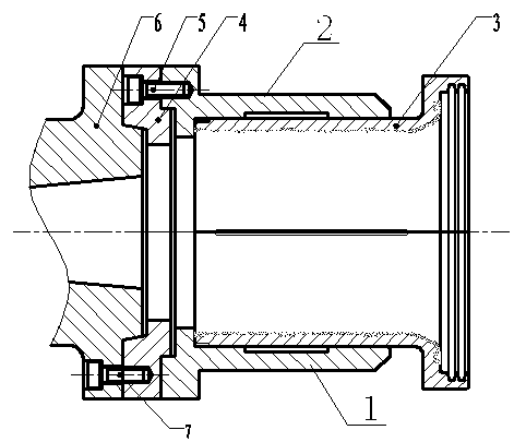
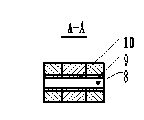
[0013] like figure 1 , 2 , 3, and 4, the processing device of the locomotive traction motor bearing bush 3 is composed of an upper carcass 2 and a lower carcass 1, and the upper and lower carcass 2, 1 are respectively a semicircular cylinder and two semicircular cylinders. Closed to form an inner cavity that matches the shape of the bearing bush 3, one connecting edge of the upper and lower tires 2, 1 is flexibly connected by a pin, and the other connecting edge is fixedly connected by a bolt; the upper and lower tires are connected by a pin. The carcass 2, 1 is respectively provided with a fixed sleeve 10, and the fixed sleeve 10 on the upper and lower carcass 2, 1 is connected together by the fixed pin 8, and another fixed sleeve 9 is set on the fixed pin 8, and the upper and lower carcass 2, 1 are connected together. The lower carcass 2, 1 can be opened and closed around the fixed pin 8; the other connecting edge of the upper and lower carcass 2, 1 is connected by bolts: a...


PUM


Abstract

The invention discloses a locomotive traction motor axle suspension bush machining device, relates to devices for finish machining of an inner circle surface of an axle suspension bush of a locomotive traction motor, and mainly aims at solving the problems that due to the fact that an existing axle suspension bush is in the structure of two semi-circles, the existing axle suspension bush has certain deformation in a natural state after being machined so that the working performance of the existing axle suspension bush is affected, and the hidden danger of adhesion of the existing axle suspension bush and serious shaft locking in a running process can be caused. According to the locomotive traction motor axle suspension bush machining device, an upper tire body and a lower tire body form an inner cavity which is matched with the axle suspension bush in shape, one connecting edge of the upper tire body and one connecting edge of the lower tire body are connected through a hinge pin, the other connecting edge of the upper tire body and the other connecting edge of the lower tire body are fixedly connected through a bolt. Due to the fact that the closed space formed by the upper tire body and the lower tire body is in a hollow cylindrical shape and completely simulates an installing surface of the axle suspension bush of the locomotive traction motor, the axle suspension bush to be machined is installed in the inner circle surface formed by the upper tire body and the lower tire body in the machining process, and therefore the operation reliability of the axle suspension bush is improved, and the accidents of the adhesion of the axle suspension bush and the shaft locking in the running process are eradicated. The locomotive traction motor axle suspension bush machining device is simple to install, convenient to machine and capable of guaranteeing machining quality.

Description

technical field [0001] The invention relates to a bearing bush processing device of a traction motor of a locomotive, which is mainly used for finishing the inner circular surface of a Babbitt alloy of a traction motor of a locomotive traction motor. Background technique [0002] Usually, the suspension of the locomotive motor shaft and the car body is connected by rolling bearings or sliding bearings. The sliding bearing connection has the characteristics of high bearing capacity, good shock resistance, stable and reliable operation, low noise, and long life. It is widely used in locomotive motor drive system. Because the bearing capacity of the bearing pad of the locomotive motor is large, the working environment is harsh, and the lubrication is poor during the start-up process, the contact accuracy between the Babbitt alloy layer of the bearing pad and the locomotive wheel axle is extremely critical. The shape and working accuracy of the inner surface directly affect the...

Claims


Application Information

Patent Timeline
IPC IPC(8): B23Q3/12
Inventor 罗隆满
Owner 襄阳中车电机技术有限公司
Why Eureka
Try Eureka