Double-terminal fault location method and double-terminal fault location system for transmission line

A technology of fault location and transmission line, applied in the field of power system, can solve problems such as low fault handling efficiency

Inactive Publication Date: 2013-06-26
AEROSPACE SCI & IND SHENZHEN GROUP
View PDF6 Cites 14 Cited by
  • Summary
  • Abstract
  • Description
  • Claims
  • Application Information

AI Technical Summary

Problems solved by technology

[0005] The technical problem to be solved by the present invention is to provide a method and system for double-terminal fault distance measurement of transmission lines with high fault processing efficiency in view of the defect of low fault processing efficiency in the prior art

Method used


Image

  • Double-terminal fault location method and double-terminal fault location system for transmission line
  • Double-terminal fault location method and double-terminal fault location system for transmission line
  • Double-terminal fault location method and double-terminal fault location system for transmission line

Examples


Embodiment 1

[0087] It should be explained that the transmission line in the power system includes phase A, phase B and phase C, and the first fault location device and the second Fault distance measuring device; Compared with the existing scheme, there is a double-ended distance measuring device in this scheme, which can quickly collect the voltage data and current data of the fault point (mentioned in the following step S1), in this embodiment, Assume that the M end of the transmission line is provided with a first fault location device, and the N end of the transmission line is provided with a second fault location device.

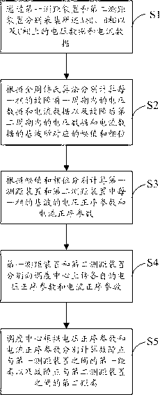
[0088] see figure 1 , figure 1 It is the flow chart of the method for fault distance measurement at both ends of the transmission line of the present invention, as figure 1 As shown, the method includes the following steps:

[0089] In step S1, the voltage data and current data on phase A, phase B and phase C are respectively collected by the first fault distance...

Embodiment 2

[0097] Taking phase A of the transmission line as an example, the specific implementation process of the above scheme is described in detail:

[0098] In said step S1,

[0099] use the formula Indicates the voltage data and current data collected by the first fault distance measuring device and the second fault distance measuring device in phase A;

[0100] Wherein, x(t) is voltage data or current data at time t; Indicates the attenuated DC component at time 0; the w value is the angular frequency of the fundamental component, and N is the number of harmonics; is the decay time constant; , respectively Amplitude and phase angle of the subharmonic.

[0101] The step S2 is specifically:

[0102] First, from the principle of Fourier series The time-domain expressions of the real and imaginary parts of each harmonic component in

[0103] Real

[0104] imaginary part

[0105] in , is the period of the fundamental frequency component, is the angular frequen...

Embodiment 3

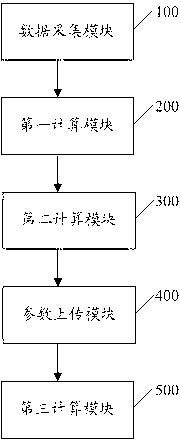
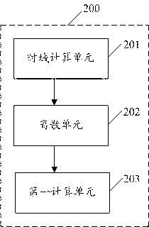
[0143] Correspondingly, the system structure corresponding to the implementation process of Embodiment 1 is as follows figure 2 As shown, the system for fault location at both ends of transmission lines includes a data acquisition module 100 , a first calculation module 200 , a second calculation module 300 , a parameter upload module 400 and a third calculation module 500 connected in sequence. The following describes the functions of each module in detail:

[0144] The data acquisition module 100 is configured to collect the voltage data and current data on the phase A, the phase B and the phase C respectively through the first fault distance measuring device and the second fault distance measurement device.

[0145] The formula is adopted in the data acquisition module 100 representing said voltage data and current data;

[0146] in, To attenuate the DC component; is the decay time constant; , respectively Amplitude and phase angle of the subharmonic.

[0147]...


PUM


Abstract

The invention discloses a double-terminal fault location method and a double-terminal fault location system for a transmission line. The transmission line comprises a phase A, a phase B and a phase C, and a first fault location device and a second fault location device which are used for monitoring fault points on the transmission line are respectively arranged at two ends of the transmission line. The double-terminal fault location method includes acquiring voltage data and current data at a high speed via the double-terminal fault location devices; performing complete-cycle Fourier algorithm for the voltage data and the current data which are acquired within a cycle before a fault of each phase and the voltage data and the current data which are acquired within a second cycle after the fault of the phase; and uploading voltage positive-sequence parameters and current positive-sequence parameters which are acquired via computation to a dispatching center so that a fault location can be computed. According to the technical scheme, the double-terminal fault location method and the double-terminal fault location system have the advantages that the fault location efficiency can be improved, and problems of faults can be timely solved.

Description

technical field [0001] The invention relates to the field of electric power systems, in particular to a method and system for distance measurement of double-terminal faults of transmission lines. Background technique [0002] The fault location device is generally applicable to power units such as 110kv and above substations and power plants, and is used for fault recording, real-time monitoring and fault analysis of transmission lines. When the power system is running normally, the normal operation recording is performed, and various operating parameters and electrical quantities are monitored and analyzed in real time; when the power system fails or the operating parameters exceed the set value, the automatic start-up device performs fault recording, For future fault analysis and fault location. The fault location device is a reliable tool for real-time operation monitoring, fault analysis and distance measurement of the power system, and a powerful measure to ensure the ...

Claims


Application Information

Patent Timeline
Patent Type & Authority Applications(China)
IPC IPC(8): G01R31/08
CPCY04S10/52
Inventor 吴晓娜
Owner AEROSPACE SCI & IND SHENZHEN GROUP
Why Eureka
Try Eureka