
Machine vision system program editing environment including synchronized user interface features

A user interface, machine vision detection technology, applied in general control systems, program control, program control devices, etc., can solve problems such as identification difficulties, appropriate association difficulties, and complexity.

Active Publication Date: 2013-06-26
MITUTOYO CORP
View PDF11 Cites 11 Cited by
  • Summary
  • Abstract
  • Description
  • Claims
  • Application Information

AI Technical Summary

Problems solved by technology

Moreover, the learning mode user interface (for part program creation and editing) of this system may be particularly complex, requiring simultaneous display of a real-time image window, a video toolbar display, a part program presentation window, and a result output window (abbreviated as result Window), Inspection Feature Graphical Display Window, Position Window, Illumination Window, and Measurement Tool Display, so that users can correctly evaluate the cause and effect of their program behavior to create high-quality part processing programs
In such an editing environment, it may be difficult to simply identify all result locations associated with a part program instruction
If the user stores a partially completed part program and recalls the part program some time later to change or complete the programming, identify the appropriateness between the part program instructions and their associated effects reflected in the different windows Association can be more difficult

Method used


Image

  • Machine vision system program editing environment including synchronized user interface features
  • Machine vision system program editing environment including synchronized user interface features
  • Machine vision system program editing environment including synchronized user interface features

Examples


Embodiment Construction

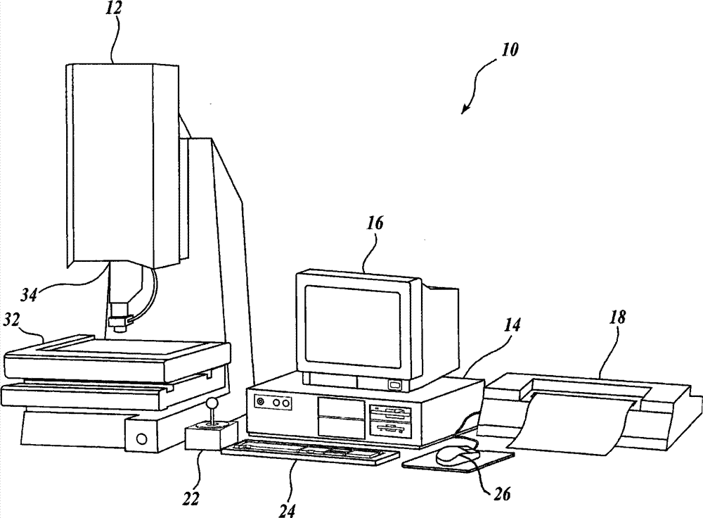
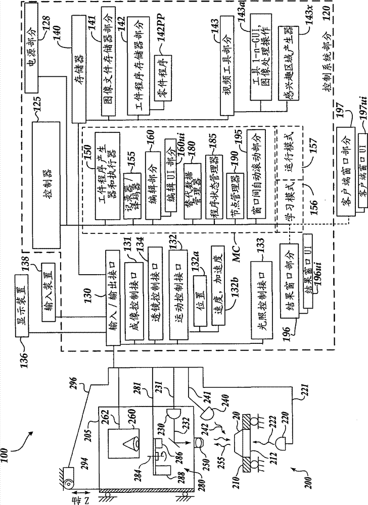
[0039] figure 1 is a block diagram of one example of a machine vision inspection system 10 for use in accordance with the methods described herein. The machine vision inspection system 10 includes a vision measuring machine 12 operatively connected to exchange data and control signals with a control computer system 14 . The control computer system 14 is further operatively connected to exchange data and control signals with a monitor or display 16, a printer 18, a joystick 22, a keyboard 24, and a mouse 26, among others. The monitor or display 16 may display a user interface suitable for controlling and / or programming the operation of the machine vision inspection system 10 .

[0040] The vision measuring machine 12 includes a movable workpiece stage 32 and an optical imaging system 34, which may include a zoom lens or an interchangeable lens. The zoom or interchangeable lenses typically provide different magnifications for the images provided by the optical imaging system 3...


PUM


Abstract

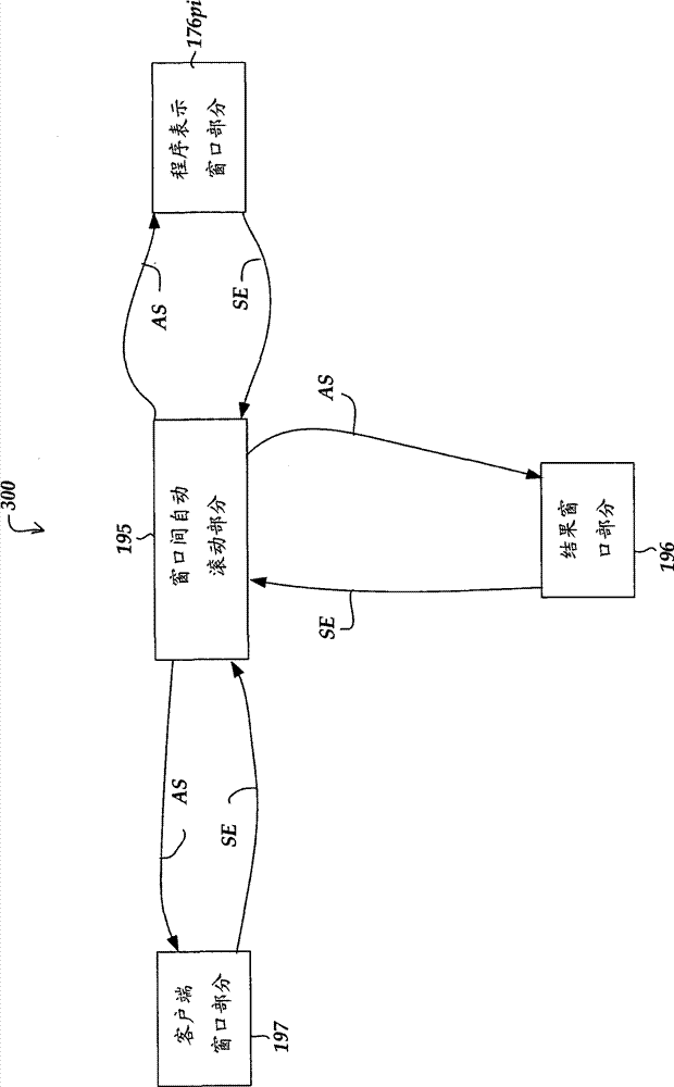
A machine vision system program editing environment including synchronized selection and / or identification of related features in a plurality of different user interface windows is provided. In particular, one of the windows is an editing window where a part program representation is displayed for editing by a user. In one embodiment, a user may select data or another feature of interest in a window that is not the editing window (e.g., a results window, or graphical workpiece inspection feature display window) and the associated part program instruction representation is automatically highlighted and / or selected in the editing window. Conversely, a part program instruction representation may be selected by a user in the editing window and the associated results or feature in another window is automatically highlighted and / or selected. User interface navigation, rapid program quality assessment, and overall part program creation and editing efficiency are significantly enhanced in such an editing environment.

Description

[0001] Cross References to Related Applications [0002] This application claims the benefit and priority of US Provisional Patent Application No. 61 / 560,278, filed November 15, 2011, and US Patent Application No. 13 / 297,232, filed November 15, 2011. technical field [0003] The present invention relates generally to machine vision inspection systems, and more particularly to methods of creating and editing part machining programs in such systems. Background technique [0004] Precision machine vision inspection systems (or simply "vision systems") can be used to obtain precise dimensional measurements of inspected objects and to detect various other object characteristics. Such a system may include a computer, camera and optics, and a precision workpiece stage that is movable in multiple directions so as to allow the camera to scan features of the workpiece being measured. An exemplary prior art system commercially available is the QUICK (Quick Vision) series of PC-based...

Claims


Application Information

Patent Timeline
IPC IPC(8): G06F9/44
CPCG01N21/8806G05B19/409G05B19/4093G05B2219/35505G05B2219/36143G05B2219/36172G05B2219/37208G05B2219/37439G05B2219/37455G06T7/0004G06T2207/20092Y02P90/02
Inventor B·塞勒R·诺斯拉普A·塔卡达K·阿里加
Owner MITUTOYO CORP
Learn More