Direct-current high-voltage motor rotor structure

A motor rotor, DC high voltage technology, applied in the shape/style/structure of the magnetic circuit, rotating parts of the magnetic circuit, etc., can solve the problems of shortening the service life of the bearing, speeding up the wear speed, and decreasing the hardness of the inner and outer ring materials of the bearing. Production cost, improve bearing service life, prevent bearing galvanic corrosion

Inactive Publication Date: 2013-06-26
ZHEJIANG DEYING ELECTRICAL MFG
View PDF3 Cites 1 Cited by
  • Summary
  • Abstract
  • Description
  • Claims
  • Application Information

AI Technical Summary

Problems solved by technology

The current breaks down the oil film discharge between the bearing balls and the inner and outer rings, resulting in high temperature, causing the local surface of the bearing to melt, forming spots and

Method used


Image

  • Direct-current high-voltage motor rotor structure
  • Direct-current high-voltage motor rotor structure

Examples


Example Embodiment

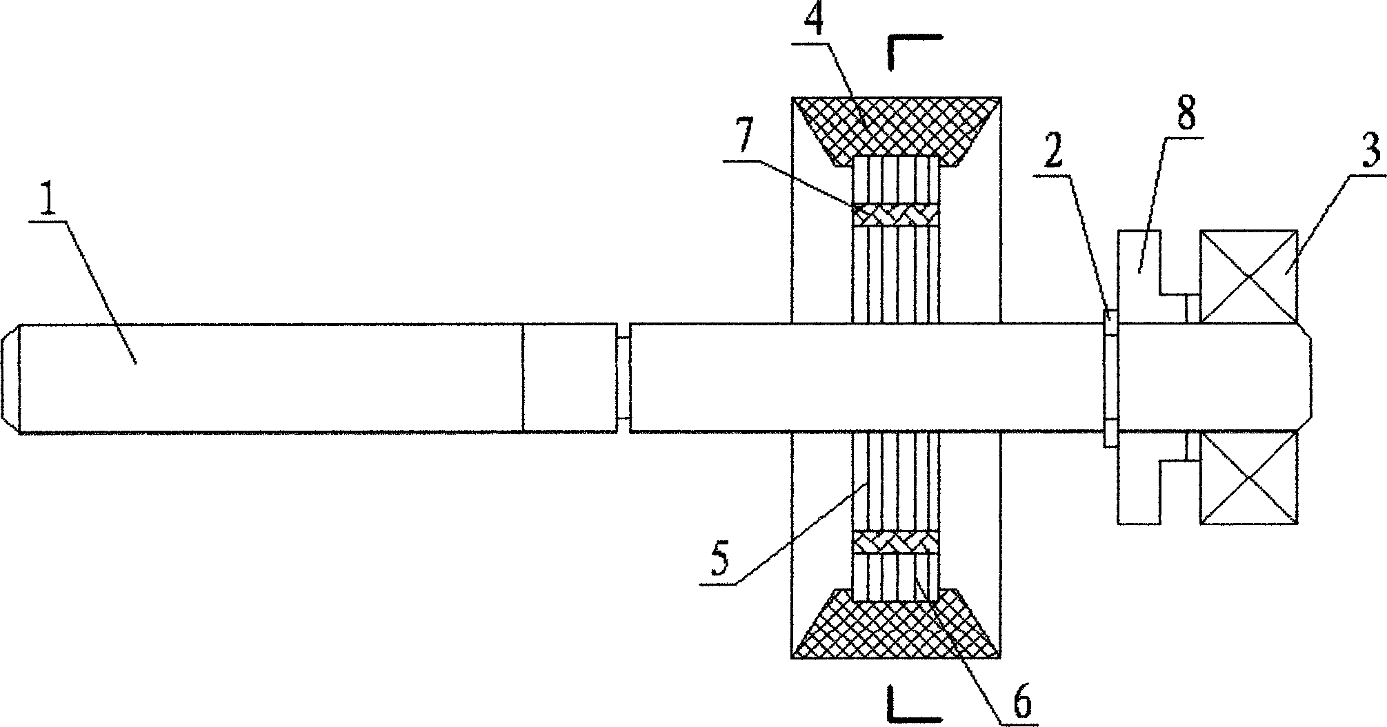
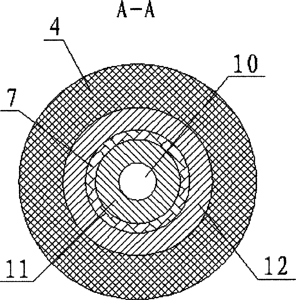
[0016] see figure 1 and figure 2 As shown, a DC high-voltage motor rotor structure of the present invention includes a rotating shaft 1, a plastic magnetic ring 2 and a bearing 3 installed on the rotating shaft 1, and an iron core sleeved on the rotating shaft 1, and is externally arranged on the The magnet 4 of the iron core, the iron core includes an inner yoke iron core 5 and an outer yoke iron core 6 that is concentric with the inner yoke iron core 5 and is arranged on the outer periphery of the inner yoke iron core 5, and the inner yoke iron core 5 and the outer yoke iron core An insulating skeleton 7 is arranged between the yoke iron cores 6, and positioning ribs (not shown) are provided on the part where the rotating shaft 1 is installed with the plastic magnetic ring 2, and the plastic magnetic ring 2 is bonded to the rotating shaft 1, and the The front end of the plastic magnetic ring 2 is mated with a retaining ring 8 .

[0017] The inner yoke iron core 5 is autom...


PUM


Abstract

The invention discloses a direct-current high-voltage motor rotor structure. The direct-current high-voltage motor rotor structure comprises a rotating shaft, a plastic magnetic ring, a bearing, an iron core and a magnet, wherein the plastic magnetic ring and the bearing are mounted on the rotating shaft, the iron core is sleeved on the rotating shaft, the magnet is externally arranged on the iron core, the iron core comprises an inner yoke iron core and an outer yoke iron core arranged on the periphery of the inner yoke iron core and concentric with the inner yoke iron core, an insulating framework is arranged between the inner yoke iron core and the outer yoke iron core, a positioning convex rib is arranged on the rotating shaft and at the position where the plastic magnetic ring is mounted, the plastic magnetic ring is adhered to the rotating shaft, and the front end face of the plastic magnetic ring is in matched connection with a stop ring. The plastic magnetic ring can be firmly fixed on the rotating shaft, so that the stop ring for limiting the bearing is omitted, and production cost is reduced; via an interruption current loop of the insulating framework arranged between the inner yoke iron core and the outer yoke iron core, shaft current is prevented from flowing to the bearing via the rotating shaft, so that electric corrosion of the bearing is effectively avoided, and service life of the bearing of a direct-current high-voltage motor is prolonged.

Description

technical field [0001] The invention relates to a rotor structure of a DC high-voltage motor. Background technique [0002] The existing magnetic ring set on the motor rotor is a sintered magnetic ring. This type of magnetic ring has poor ductility and is relatively brittle. However, the surface of the rotating shaft of the motor rotor is flat and smooth. Generally, the sintered magnetic ring is fixed on the rotating shaft with glue. The front and rear ends of the sintered magnetic ring are respectively provided with retaining rings to limit the position of the sintered magnetic ring and its rear bearing. Because the surface of the rotating shaft is flat, if the glue is not well bonded, it is easy to cause the sintered magnetic ring to shift and affect the performance of the motor. Back-up rings are installed at both ends of the sintered magnetic ring, which causes excessive production cost in mass production. Moreover, electric corrosion is more common in electric motors....

Claims


Application Information

Patent Timeline
IPC IPC(8): H02K1/27
Inventor 蒋能国杜姜
Owner ZHEJIANG DEYING ELECTRICAL MFG
Why Eureka
Try Eureka