Precise inverter circuit

An inverter circuit, a sophisticated technology, is applied in electrical components, irreversible DC power input is converted into AC power output, AC power input is converted into DC power output, etc., which can solve problems such as differences in the relationship between on-off and sine wave , to achieve the effect of reducing high-order harmonic components

Inactive Publication Date: 2013-06-26
SHAANXI ZHONGXINLIAN ENERGY SAVING NEW TECHDEV
View PDF0 Cites 1 Cited by
  • Summary
  • Abstract
  • Description
  • Claims
  • Application Information

AI Technical Summary

Problems solved by technology

[0003] Secondly, there is a difference between the on-off and sine wave relationship of the switching device in the control inverter circuit, resulting in high-order harmonics

Method used


Image

  • Precise inverter circuit
  • Precise inverter circuit
  • Precise inverter circuit

Examples


Embodiment Construction

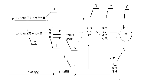
[0020] Such as figure 1 As shown, the precision inverter circuit includes: microprocessor 1, synchronous square wave generator 2, sine wave generator 3, arithmetic unit 4, biphasic SPWM5, controllable inverter bridge 6, filter circuit 7, motor 8, Voltage and current sensor 9, microprocessor 1 is electrically connected with the input port of synchronous square wave generator 2, outputs a control signal to synchronous square wave generator 2, starts the square wave signal that synchronous square wave generator 2 produces output, synchronous square wave generator 2 The wave generator 2 is divided into two circuits, one of which is electrically connected to the sine wave generator 3, and the other is electrically connected to the controllable inverter bridge 6; the sine wave generator 3 outputs a sine wave signal with a frequency of 15~50Hz, 15~50Hz The sine wave signal is sent to the operator 4, and the operator 4 controls the work of the controllable inverter bridge 6 through th...


PUM


Abstract

The invention relates to a power inverter circuit, in particular to a precise inverter circuit. The precise inverter circuit adopts an arithmetic unit 4 to output biphasic sine pulse width modulation (SPWM) signals, the SPWM signals and output square signals together control a controllable inverter bridge to work, output pulse voltage area is equal to area of selected output sine wave in a corresponding interval, and by changing frequency and amplitude of modulating wave, frequency and amplitude of output voltage of the inverter circuit can be adjusted. The voltage pulse series can greatly reduce higher harmonic components in load current.

Description

technical field [0001] The invention relates to a power inverter circuit, in particular to a precision inverter circuit. Background technique [0002] At present, the reference sine wave generation circuit required by the inverter circuit is useful for analog circuits and single-chip microcomputers. The sine wave generated by the analog circuit has poor frequency stability and is easily affected by temperature; the sine wave generation circuit controlled by the single-chip microcomputer is prone to program A runaway situation with catastrophic results. [0003] Secondly, there is a difference between the on-off and sine wave relationship of the switching device in the control inverter circuit, resulting in high-order harmonics. Contents of the invention [0004] The purpose of the present invention is to provide a precision inverter circuit with good power quality, no noise output and good reliability. [0005] The purpose of the present invention is achieved in this way...

Claims


Application Information

Patent Timeline
Patent Type & Authority Applications(China)
IPC IPC(8): H02M7/48H02M7/5387
Inventor 陈曦
Owner SHAANXI ZHONGXINLIAN ENERGY SAVING NEW TECHDEV
Why Eureka
Try Eureka