Electric utility meter comprising load identifying data processor

A technology for data processors and public utilities, applied in data processing applications, instruments, measuring electrical variables, etc., can solve problems such as the inability to make better use of non-intrusive load monitoring information

Inactive Publication Date: 2013-06-26
胜赛斯美国公司
View PDF7 Cites 13 Cited by
  • Summary
  • Abstract
  • Description
  • Claims
  • Application Information

AI Technical Summary

Problems solved by technology

[0006] While non-intrusive load monitoring has been known for many years, utilities and other interested

Method used


Image

  • Electric utility meter comprising load identifying data processor
  • Electric utility meter comprising load identifying data processor
  • Electric utility meter comprising load identifying data processor

Examples


Example Embodiment

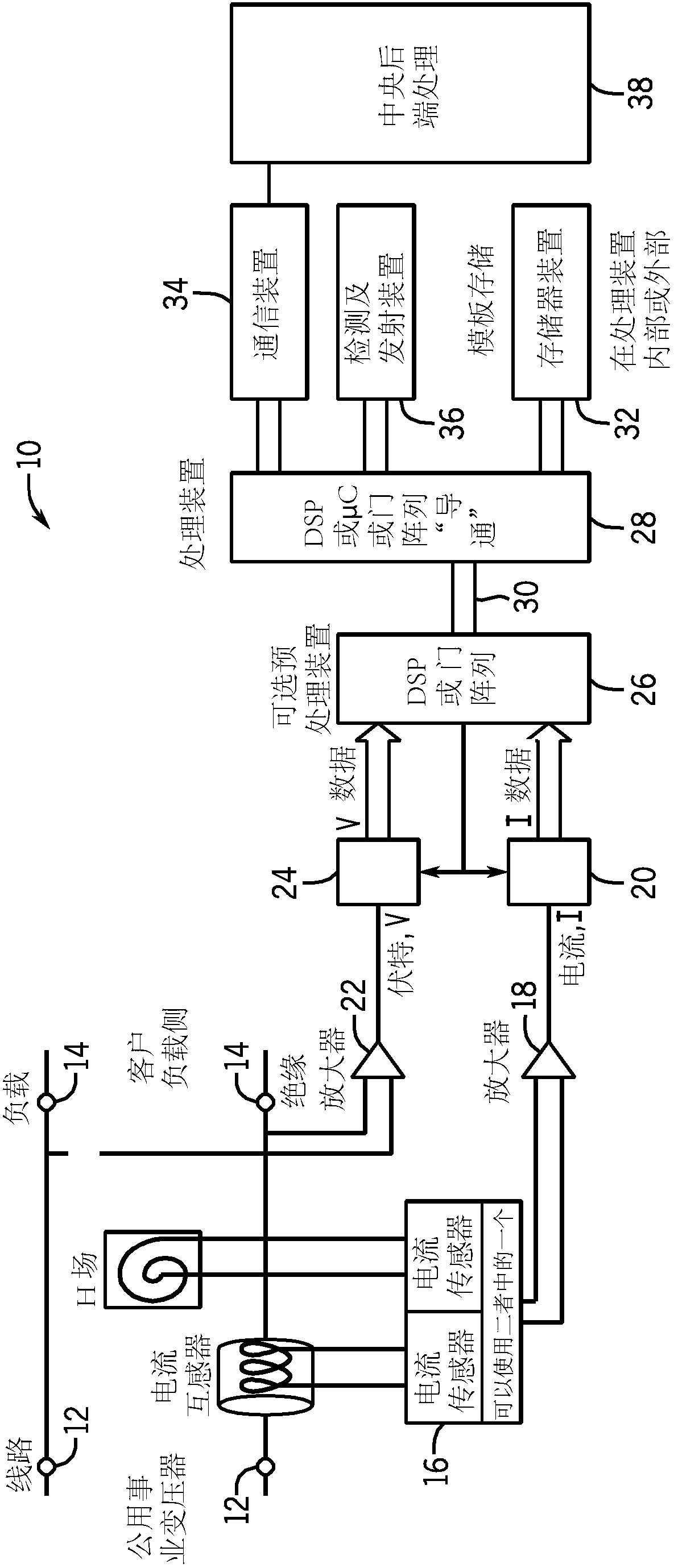
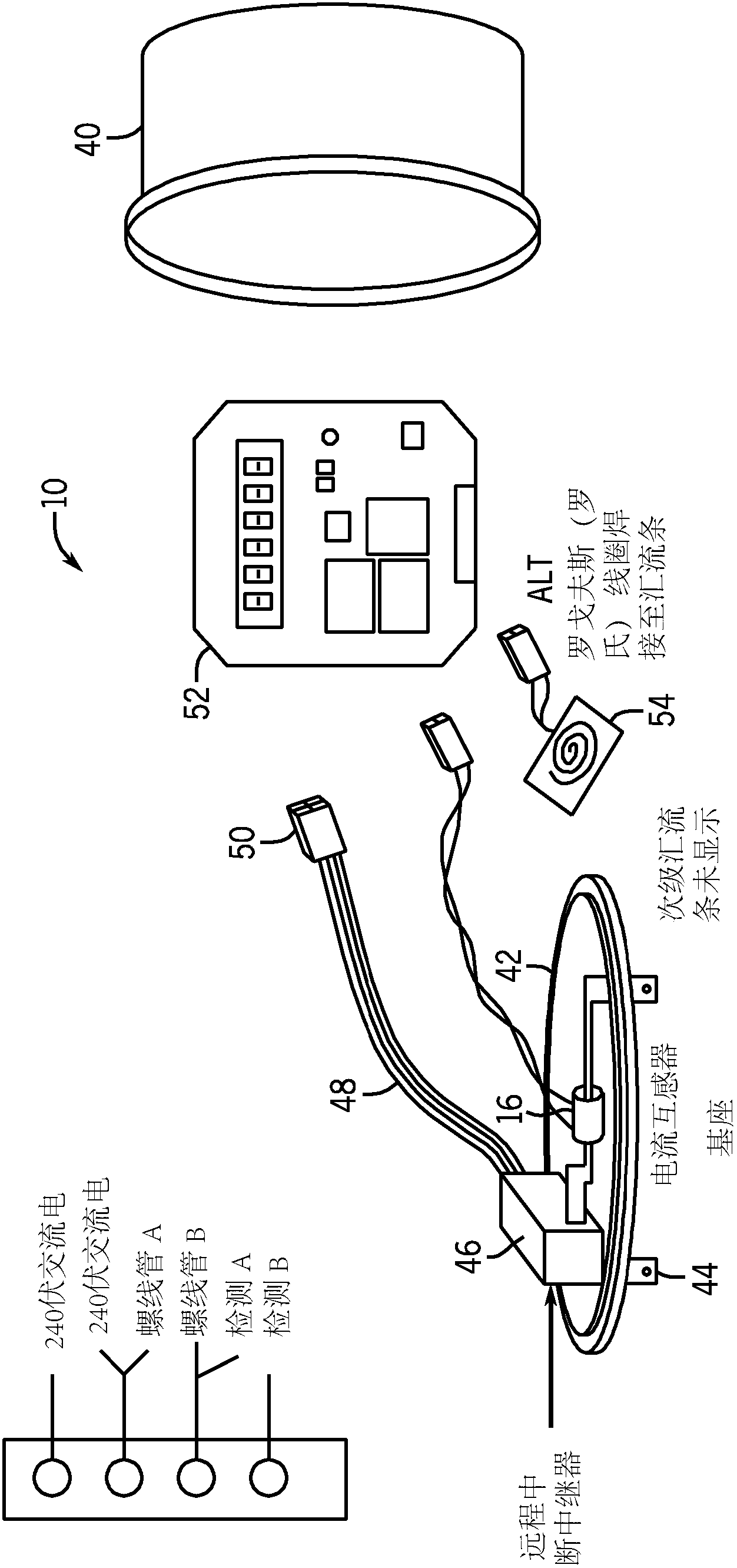
[0050] figure 1is a general schematic illustration of an enhanced electric utility meter 10 constructed in accordance with the present invention. The electricity meter 10 may be used in a residential or business environment to monitor the amount of electricity consumed by the residence or business served by the electricity meter 10 . The electricity meter 10 is typically placed between the line connection 12 and the load connection 14 . The meter includes a current sensor 16 which senses the current drawn from the line connected load. like figure 1 As shown, the current sensor 16 can be one of two different types of current sensors.

[0051] The current sensor 16 feeds the sensed current to an analog-to-digital converter 20 through an amplifier 18 . In addition to measuring the current, the voltage signal is sent via a further amplifier 22 to a second analog-to-digital converter 24 . exist figure 1 In the illustrated embodiment, the analog-to-digital converter samples...


PUM


Abstract

The present disclosure replaces a standard electric utility meter with a meter having a signal sensor, signal generator, and processor platform. The utility can then select the 'application' that best suits their analysis needs. The meter platform consists of 3 layers: physical interfaces (16 - 24, 34, 36), pre-processing resources (26), and applications processing & database (28, 32). The physical interfaces include voltage, current, and load sensors, radio and PLC communications, optical, and power control for advanced outage management. The increased processing capabilities combined with signal and data processing allow for true distributed intelligence in the smart grid. The physical layer, pre-processing DSP and firmware form open APIs for third party developers.

Description

[0001] Cross References to Related Applications [0002] This application is based on, and claims priority from, US Provisional Patent Application No. 61 / 372,344, filed August 10, 2010. technical field [0003] The present invention generally relates to a method and system for monitoring load characteristics of electrical loads with an electric meter in a residential or business environment and for identifying specific types of loads and their respective operating conditions. More specifically, the present invention relates to a method for monitoring the load characteristics of electrical loads and communicating identifying information associated with each load to a system operator or a third party for inspection, analysis, and possibly communicating information directly to the operator of the electrical load / Owner's methods and systems. Background technique [0004] Electric utilities in commercial facilities need to monitor details of their customers' electricity consu...

Claims


Application Information

Patent Timeline
IPC IPC(8): G01D4/00G06Q50/06
CPCG01D4/004G01R22/10G06Q50/06G01D2204/24Y02B90/20Y04S20/30
Inventor H·布里顿·桑德福特罗伯特·J·鲁盖特
Owner 胜赛斯美国公司
Why Eureka
Try Eureka