Automatic feeding device for stud welding

A technology of automatic feeding and pushing device, applied in welding equipment, arc welding equipment, manufacturing tools, etc., can solve the problems of increasing production costs, low efficiency, waste of electric energy, etc., to save production costs, improve work efficiency, and save electric energy. Effect

Active Publication Date: 2013-07-03
佛山市玛雅数控设备有限公司
View PDF6 Cites 18 Cited by
  • Summary
  • Abstract
  • Description
  • Claims
  • Application Information

AI Technical Summary

Problems solved by technology

This kind of feeding method is not only inefficient, but also prone to clogging of workpieces. At the same time, the noise of the air compressor is large, and it also wastes electric energy and increases production costs. It is not suitable for the current market demand.

Method used


Image

  • Automatic feeding device for stud welding
  • Automatic feeding device for stud welding
  • Automatic feeding device for stud welding

Examples


Embodiment 1

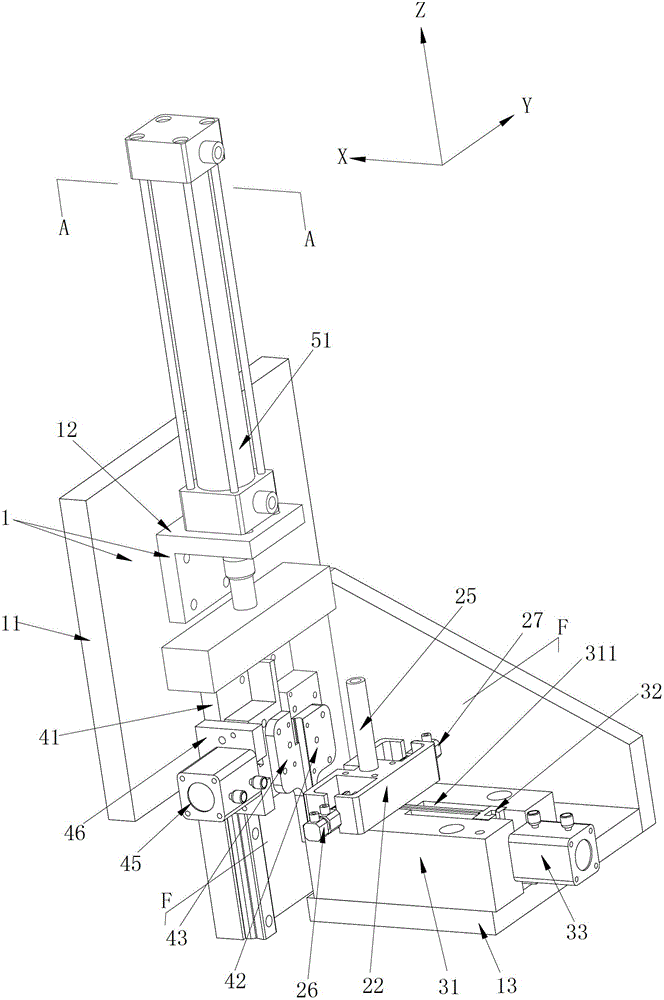
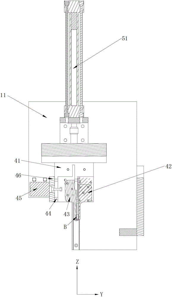
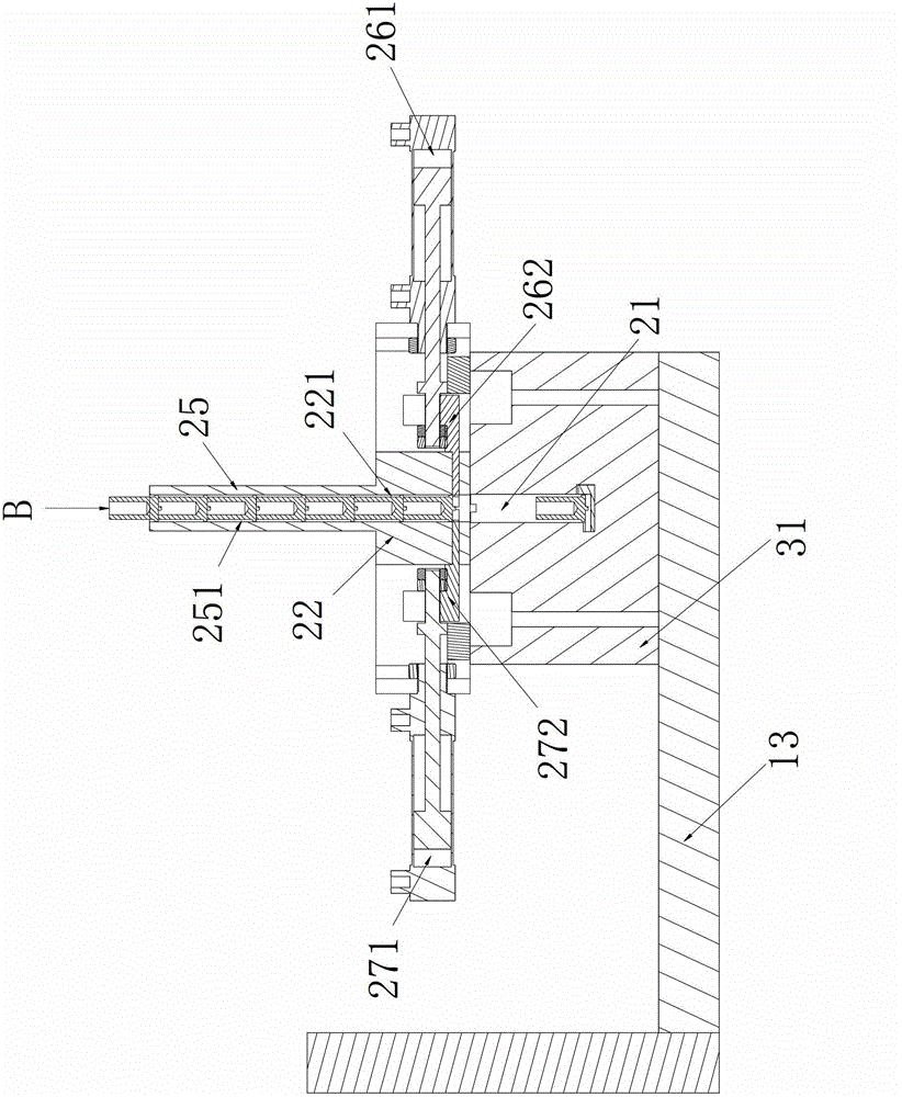
[0049] Figure 1 to Figure 11 Shown is the structure of the first embodiment of the stud welding automatic feeding device of the present invention, including a frame 1, which is used to place the longitudinal discharge device of the stud B to be welded, and is used to install the vertical discharge device and can be used in The horizontal pushing device that moves back and forth horizontally between the first position and the second position of the horizontal station of the frame 1, and the longitudinal push that can move back and forth longitudinally between the third position and the fourth position of the vertical station of the frame 1 device, which is fixed at the lower end of the longitudinal pushing device and clamps the movable clamp of the stud B pushed to the second position by the horizontal pushing device when the longitudinal pushing device moves to the third position, and is used for data transmission to connect the vertical discharging The controller (T (figure ...

Embodiment 2

[0074] Figure 12 Shown is the structure of the second embodiment of the stud welding automatic feeding device of the present invention, which is the same as Figure 1 to Figure 11 The only differences in the structure of the first embodiment shown are:

[0075] In order to realize the multi-station feeding function, specifically, the number of the longitudinal discharging device is multiple, and the number of the horizontal pushing device is multiple, and the vertical discharging device corresponds to the horizontal pushing device one by one The automatic feeding device for stud welding also includes a screw drive device for transferring the horizontal pushing device to the horizontal station one by one; the screw drive device is connected to the controller through data transmission.

[0076] Specifically, the screw drive device includes a support plate 61, a screw 62 extending vertically, and a servo motor 63 for driving the screw 62 to rotate under the action of the contro...


PUM


Abstract

The invention discloses an automatic feeding device for stud welding. The automatic feeding device for stud welding comprises a machine frame, a longitudinal placing device for placing studs to be welded, a transverse pushing device for installing the longitudinal placing device and capable of transversely moving back and forth between a first position and a second position of a horizontal workstation of the machine frame, a longitudinal pushing device capable of longitudinally moving back and forth between a third position and a fourth position of a vertical workstation of the machine frame, a movable clamp fixed at the lower end of the longitudinal pushing device and capable of clamping a stud pushed to the second position by the transverse pushing device when the longitudinal pushing device moves to the third position, and a controller for performing data transmission and connected with the longitudinal placing device, the transverse pushing device, the longitudinal pushing device and the movable clamp. The automatic feeding device for stud welding is high in working efficiency, free of workpiece blockage, small in noise and electricity-saving, and can help to save the production cost.

Description

[0001] technical field [0002] The invention relates to the technical field of automatic feeding devices, in particular to an automatic feeding device for stud welding. [0003] Background technique [0004] The stud welding methods on the market generally adopt two methods. The first method is to use manual welding. Specifically, the studs are placed on the workpiece, and the studs are welded to the workpiece by a pulse welding machine. Such a welding method has low work efficiency, cannot meet market demand, and is prone to industrial accidents. And another way is to adopt automatic welding machine to weld the stud on the workpiece, but the feeding method of this automatic welding machine is generally to adopt air compressor to blow the stud to the welding chuck. Such a feeding method is not only inefficient, but also prone to clogging of workpieces. At the same time, the noise of the air compressor is large, and it also wastes electric energy and increases production c...

Claims


Application Information

Patent Timeline
Patent Type & Authority Applications(China)
IPC IPC(8): B23K9/12
Inventor 王金领
Owner 佛山市玛雅数控设备有限公司
Why Eureka
Try Eureka