
Variable-temperature-field displacement simulator for multi-thermal fluid

A multi-component thermal fluid and displacement simulation technology, applied in the direction of production fluid, measurement, wellbore/well components, etc., can solve the problem that pressure and temperature cannot realize multi-point real-time automatic collection and storage, affect the viscosity of crude oil and the properties of oil-water interface, It cannot reflect heat conduction and other issues, and achieves the effect of enhancing reliability and reference value, reliable and practical data, and improving oil displacement efficiency

Inactive Publication Date: 2013-07-03
CHINA PETROLEUM & CHEM CORP +1
View PDF9 Cites 12 Cited by
  • Summary
  • Abstract
  • Description
  • Claims
  • Application Information

AI Technical Summary

Problems solved by technology

This conventional method has the following three shortcomings: 1) It cannot form a temperature field in the displacement direction, and cannot reflect the heat conduction phenomenon that occurs in the actual reservoir development. There is often a temperature difference between reservoir rocks, and the heat conduction caused by the temperature difference is particularly obvious in the thermal recovery of heavy oil; 2) Temperature affects the viscosity of crude oil and the properties of the oil-water interface, and conventional methods cannot control the influence of temperature on crude oil and injected fluids. 3) Most of the pressure and temperature in conventional oil displacement experiment methods cannot realize multi-point real-time automatic collection and storage

Method used


Image

  • Variable-temperature-field displacement simulator for multi-thermal fluid

Examples


Embodiment Construction

[0018] In order to make the above and other objects, features and advantages of the present invention more comprehensible, preferred embodiments are listed below and described in detail in conjunction with the accompanying drawings.

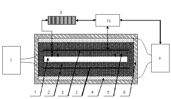
[0019] Such as figure 1 as shown, figure 1 It is a structural diagram of the variable temperature field multi-element thermal fluid displacement simulation device of the present invention. The variable temperature field multivariate thermal fluid displacement simulation device consists of a one-dimensional sand filling model 1, a sand bath 2, a preheating system 3, an oil bath circulation system 4, a temperature measurement and pressure measurement system 5, a thermal insulation device 6, and a preheating control system 7. The oil bath temperature adjustment system 8, the data acquisition system 9 and the computer 10 are composed.

[0020] The one-dimensional sand packing model 1 is placed in the center of the sand bath 2, in which oil sand or ...


PUM


Abstract

The invention provides a variable-temperature-field displacement simulator for a multi-thermal fluid, which comprises a one-dimensional sand pack, a sand bath, an oil bath circulatory system and an oil bath temperature adjusting system, wherein the one-dimensional sand pack is filled with experimental oil sand or quartz sand so as to simulate the physical characteristics of an oil reservoir; the sand bath is filled with quartz sand or oil reservoir sand so as to simulate the physical environment of the reservoir; the oil bath circulatory system is used for adjusting the temperature of the outer boundary of the sand bath; and the oil bath temperature adjusting system is used for calculating and following up the temperature of the oil bath circulatory system automatically according to the heat conduction in the sand bath and the oil bath circulatory system. The variable-temperature-field displacement simulator for the multi-thermal fluid solves the problems of various unreasonable conditions, modes and methods existing in experimental modes that an experimental body is placed in high-temperature isoperibol for reservoir oil displacement of the multi-thermal fluid and are adopted in heavy oil thermal recovery simulation experiments in the conventional petroleum industry, and improves the similarity between indoor experimental conditions and the field, thereby enhancing the reliability degree and the reference value of experimental results.

Description

technical field [0001] The invention relates to a device for multi-element thermal fluid flooding experiment, in particular to a variable temperature field multi-element thermal fluid displacement simulation device. Background technique [0002] At present, in the physical simulation experiments involved in the petroleum industry, the existing conventional methods are carried out in a constant temperature environment. Before the displacement, the ambient temperature is raised to the experimental temperature, and then the displacement experiment is carried out with saturated crude oil. This conventional method has the following three shortcomings: 1) It cannot form a temperature field in the displacement direction, and cannot reflect the heat conduction phenomenon that occurs in the actual reservoir development. There is often a temperature difference between reservoir rocks, and the heat conduction caused by the temperature difference is particularly obvious in the thermal r...

Claims


Application Information

Patent Timeline
Patent Type & Authority Applications(China)
IPC IPC(8): E21B47/00E21B43/24
Inventor 李振泉王胜曹绪龙许坚闵令元于春磊曲岩涛孙宝泉李奋刘华夏张莉莉杨伟宇
Owner CHINA PETROLEUM & CHEM CORP
Learn More