Control valve having a variable nozzle cross-section for automatic compressed-air brakes

A technology of compressed air and control valves, which is applied in the direction of brakes, automatic starting devices, control valves and air release valves, etc., which can solve the problems of dangerous longitudinal force of trains and ineffective acceleration of signal transmission, so as to achieve high operation safety and realize operation Safety, avoiding the effect of dangerous longitudinal forces

Inactive Publication Date: 2013-07-03
KNORR BREMSE SYST FUR SCHIENENFAHRZEUGE GMBH
View PDF5 Cites 9 Cited by
  • Summary
  • Abstract
  • Description
  • Claims
  • Application Information

AI Technical Summary

Problems solved by technology

[0009] Dangerous longitudinal forces can occur in trains when signal transmission in the t...

Method used


Image

  • Control valve having a variable nozzle cross-section for automatic compressed-air brakes
  • Control valve having a variable nozzle cross-section for automatic compressed-air brakes
  • Control valve having a variable nozzle cross-section for automatic compressed-air brakes

Examples


Embodiment Construction

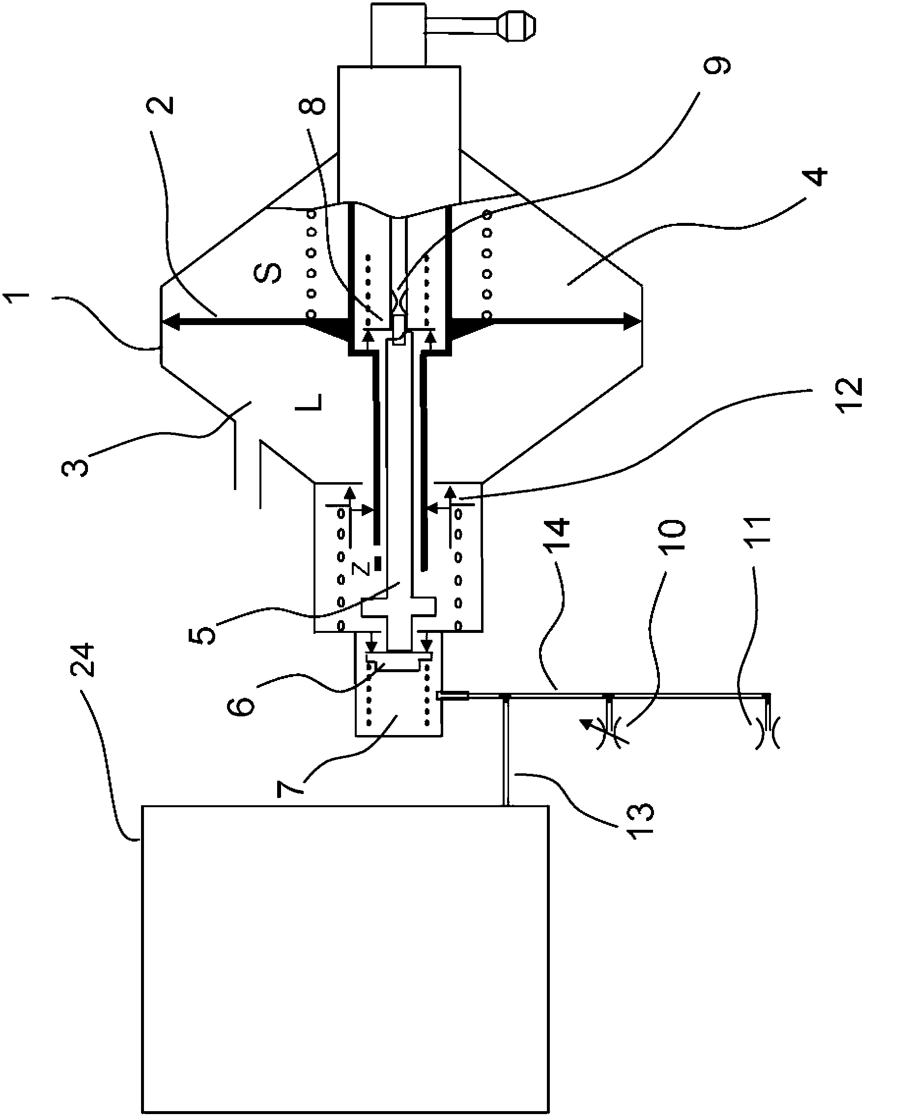
[0037] according to figure 1 The dual pressure unit 1 shown here, also called line valve, of the pneumatic control valve has a control piston 2 which is acted upon from one side with main air line pressure L via a first control chamber 3 . The reference pressure S present in the associated second control chamber 4 acts on the control piston 2 from the opposite side. Protruding from the control piston 2 is a rod 5 which actuates an accelerator valve 6 with its end.

[0038] The rod 5 is supported here on a vent valve 8 for the reference pressure S, which is held closed by a compression spring. This stage clip is stronger than the stage clip of accelerator valve 6, so accelerator valve is opened at first. By opening the accelerator valve 6 with the rod 5 of the control piston 2, braking acceleration takes place by additionally compressing air from the main air line L via the non-return valve 12 and the channel KZE7 integrated in the line part 1 (additional row air passage) in...


PUM


Abstract

The invention relates to a control valve for indirectly acting compressed-air brakes of railway vehicles, containing a triple-pressure element (24) and a twin-pressure element (1), which comprises a control piston (2; 2'), on which from one side the pressure of the air of a main air line (L) acts and from the opposite side the pressure of the air of a valve spool chamber (S) acts and which interacts with an acceleration valve (6) via a tappet (5), which, in the open state, connects the main air line (L) via a check valve (12), and connects the valve spool chamber (S) via a valve (8; ; 8') or via a bore (9), to a channel (7), and further to a channel (13) for the additional ventilation at the start of braking via the triple-pressure element (24) and to a ventilation path (14) in the twin-pressure element (1) to the surroundings, wherein at least one throttle area (10) is arranged in the ventilation path (14), the effective cross-section of said throttle area being variable via actuation means in the twin-pressure element (1) from a closed or inactive state or from a minimum cross-section to a maximum cross-section.

Description

technical field [0001] The invention relates to a control valve for an automatic compressed air brake for a pressure in a continuous main air line of a train and a stored reference pressure derived from the pressure in the main air line The pressure difference between them forms the brake cylinder pressure. Background technique [0002] The field of application of the invention is rail vehicles. Rail vehicles generally have automatic compressed air brakes, in which a reduction in the pressure in the main air line from the normal operating pressure causes the brake cylinder pressure to build up. The transfer function of the reduced pressure in the main air line to the increased brake cylinder pressure and vice versa is performed by the control valve. The speed of transmission of pressure changes in the main air line, the gradient and uniformity of the build-up and release of brake cylinder pressure during braking and release are crucial parameters that allow long, heavy and...

Claims


Application Information

Patent Timeline
IPC IPC(8): B60T7/12B60T13/57B60T15/18B60T15/22B60T15/34B60T15/42B60T15/48B60T15/52B60T17/22B60T8/17B60T8/18B60T13/26B60T13/36B60T13/46
CPCB60T13/665B60T13/266B60T13/365B60T15/021B60T15/184B60T17/228
Inventor M·黑勒V·克里洛夫T·彼得S·罗曼诺夫
Owner KNORR BREMSE SYST FUR SCHIENENFAHRZEUGE GMBH
Why Eureka
Try Eureka