Method and apparatus for pressure testing a pipe joint

A pressure test and equipment technology, which is applied in the direction of using liquid/vacuum for liquid tightness measurement, pipe/pipe joint/pipe fitting, mechanical equipment, etc., can solve the problems of high consumption, large energy consumption, large pipeline volume, etc. Achieving good protection and low consumption

Active Publication Date: 2013-07-03
MARICAP OY
View PDF9 Cites 24 Cited by
  • Summary
  • Abstract
  • Description
  • Claims
  • Application Information

AI Technical Summary

Problems solved by technology

Due to very long pipe series and typically very large pipe diameters (pipe diameters are typically 200-500mm), pressure testing of the entire length of pipe is time consuming due to the large volume of the pipe
In addition, a large amount of liquid or gas to be used in the pressure test is consumed, pumping the liquid or gas consumes a large amount of energy

Method used


Image

  • Method and apparatus for pressure testing a pipe joint
  • Method and apparatus for pressure testing a pipe joint
  • Method and apparatus for pressure testing a pipe joint

Examples


Embodiment Construction

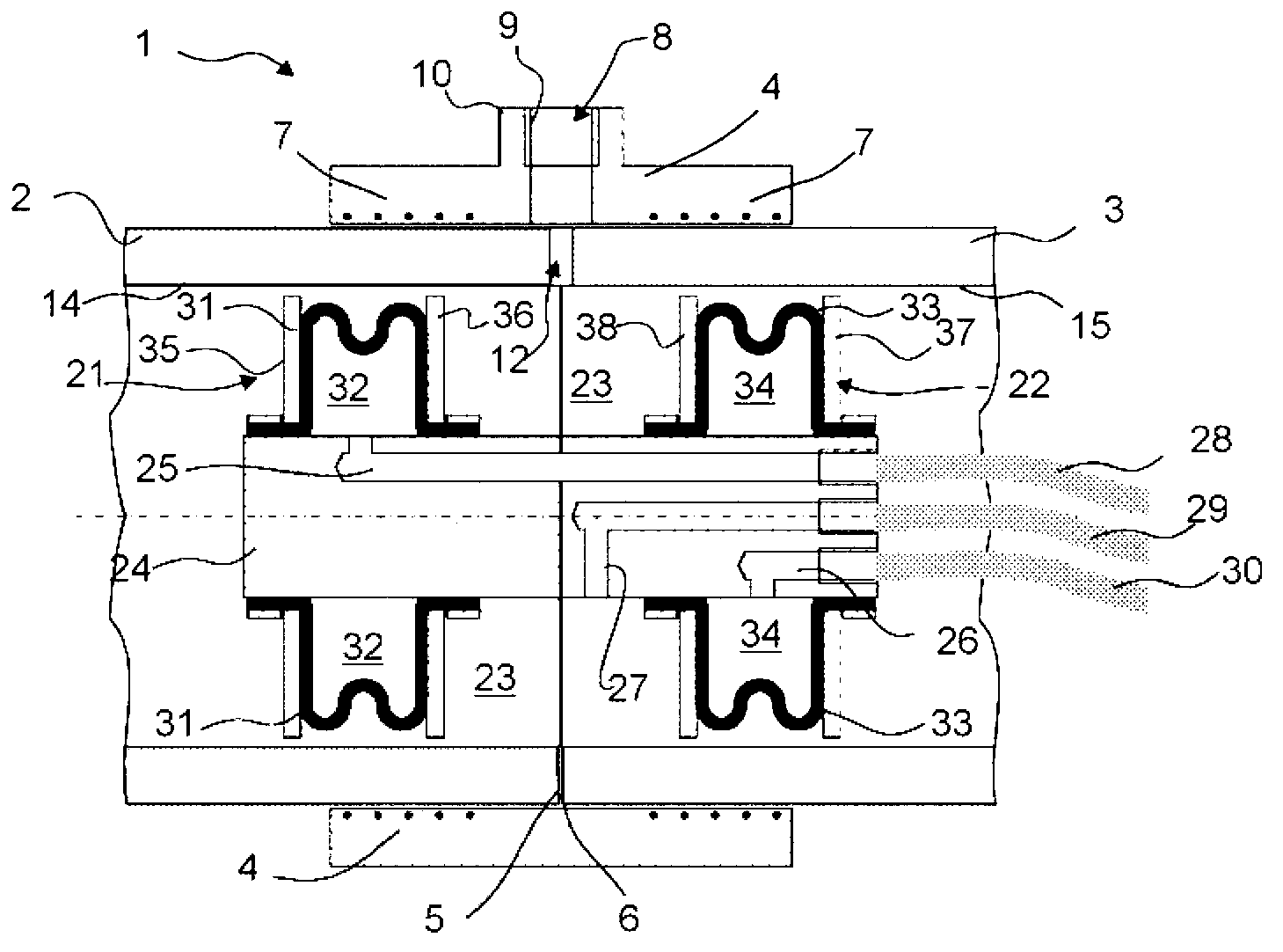
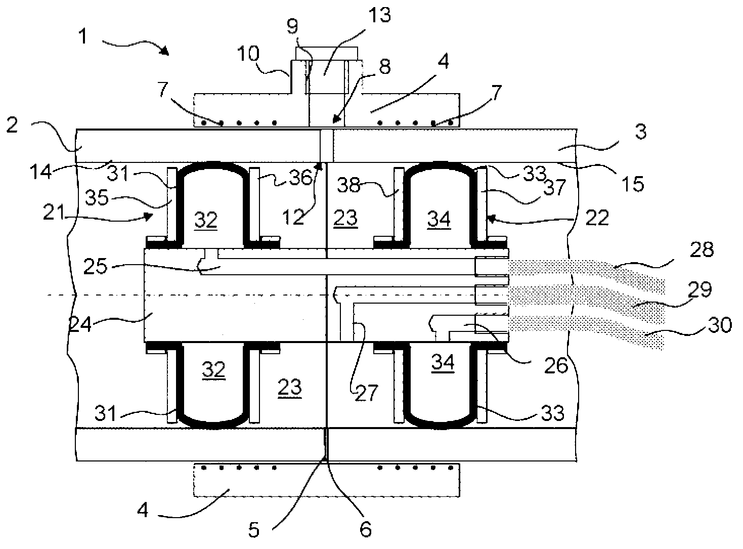
[0015] figure 1 and 2 A cutaway portion of the pipe joint 1 to which the sleeve portion 4 is applied is shown. In this joint two pipe parts 2 and 3 are joined together end-to-end, in which case the abutting end 5 of the first pipe part 2 abuts against the abutting end 6 of the second pipe part 3 . Adjacent end sections of the pipe parts 2 , 3 are arranged in bushings, ie in the sleeve part 4 . The bushing portion 4 includes heating means 7, such as thermal resistance wires 7, which become heated when electric current is conducted to them. A connection point (not shown) per se belonging to the state of the art may be arranged in the bushing part 4 , said connection point being connected to a thermal resistance wire and to which connection point the current is communicated. Due to the heating by the heating means 7 , typically a resistance wire, a joint is formed between the sleeve part 4 and the tube parts 2 , 3 in a manner known per se from the prior art. In the connection...


PUM


Abstract

Method for testing and / or for pressure testing the tightness of the joints of the transfer piping of a pneumatic pipe transport system for waste, in which method the pipe section to be tested is separated inside the pipe from the other piping and pressure medium is conducted into the section, and leaks and / or the pressure of the pressure medium are monitored on the section of pipe to be tested. In the method a device is taken inside the piping, which device comprises a first wall part (21), which comprises first sealing means (31), and a second wall part (22), which comprises second sealing means (33), in which case the pipe section to be tested, more particularly the point of connection, remains between the first wall part (21) and the second wall part (22), in which case the sealing means (31) of the first wall part are brought to be tighter to the inside surface (14) of the pipe and the sealing means (33) of the second wall part (22) are brought to be tighter to the inside surface (15) of the pipe, and pressure medium is brought into the chamber space (23) bounded by the first wall part (21) and the second wall part (22) as well as by the inside surface of the pipe section, and the pressure or a change of pressure is measured or a possible sealing defect of the pipe section is otherwise indicated.

Description

technical field [0001] The object of the invention is a method as defined in the preamble of claim 1 . [0002] The object of the invention is also a device according to claim 7 . Background technique [0003] Bushing fittings are commonly used to join pipes, more particularly plastic pipes, in an end-to-end fashion. The connection point is arranged in the bushing, i.e. in the sleeve parts, so that the ends of the pipe parts to be connected together are inside the bushing, so that the bushing is around the connection point and along both sides from the connection point. The direction extends a certain distance in the longitudinal direction of the tube. The bushing part is provided with a thermistor or equivalent, in which case, when the connection is made, the current is conducted to the resistor, in which case the resistor heats up and between the bushing part and the tube part Form joints. A problem exists with said type of joints, especially when they are used in join...

Claims


Application Information

Patent Timeline
Patent Type & Authority Applications(China)
IPC IPC(8): G01M3/28B65F5/00
CPCB29C65/7802B29C65/8246B29C66/1142B29C66/5221B29C66/5229B29C66/73921B29C66/97F16L47/03G01M3/005B29C65/3476F16L2101/30B29C65/3432B29C66/9121B29C65/02B29C66/1122G01M3/2853B65F5/005G01M3/2815G01M3/28B65F5/00
Inventor G·松德霍尔姆
Owner MARICAP OY
Why Eureka
Try Eureka