Gear shaft forming method and die adopted by same

A technology for gear shafts and molds, which is applied in the direction of manufacturing tools, mechanical equipment, engine components, etc., can solve the problems of low processing efficiency and low processing accuracy, and achieve the effect of improving production efficiency.

Active Publication Date: 2013-07-10
浙江鼎盛汽车紧固件有限公司
View PDF9 Cites 14 Cited by
  • Summary
  • Abstract
  • Description
  • Claims
  • Application Information

AI Technical Summary

Problems solved by technology

[0003] The purpose of the present invention is to provide a method for forming a gear shaft and a mold used for it, which can improve the machining accuracy and efficiency of the gear shaft, in view of the disadvantages of low processing efficiency and low processing precision in the prior art when upsetting a gear shaft

Method used


Image

  • Gear shaft forming method and die adopted by same
  • Gear shaft forming method and die adopted by same
  • Gear shaft forming method and die adopted by same

Examples


Embodiment Construction

[0024] Below in conjunction with accompanying drawing and embodiment the present invention will be further described:

[0025] Taking the processing of a gear shaft with a gear at one end and a spline at the other end as an example, the molding method of the present invention and the specific structure of the mold are described in detail, so as to facilitate the understanding of the molding method of the gear shaft of the present invention and the structure of the mold used.

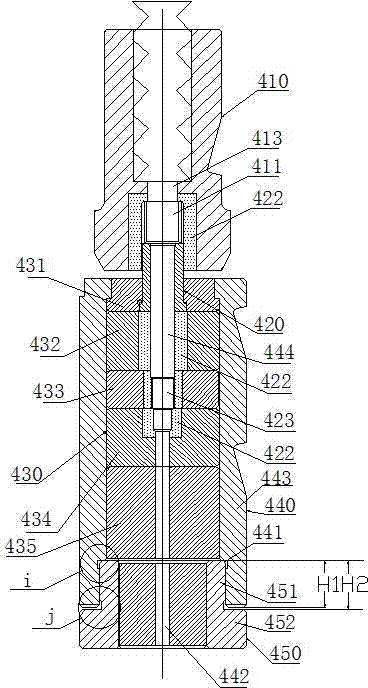
[0026] Such as figure 1 As shown, the upsetting mold for finally shaping the gear shaft of the present invention includes a die 410 , a main die 440 and a die cover 450 .

[0027] In the die 410, a die cavity 411 matching the outer surface shape of the gear cylinder of the gear shaft is provided, and a front rod hole 413 communicated with the die cavity 411 for the front rod to pass through;

[0028] In the main mold 440, a main mold cavity 444 matching the shaft portion of the gear shaft and the cylind...


PUM


Abstract

The invention aims at the defects of low processing efficiency and low machining precision when a gear shaft is upset in the prior art, and provides a gear shaft forming method and die adopted by the same. The die comprises a stamping die and a main die, wherein a stamping die cavity matched with the outer surface shape of a gear of the gear shaft is formed in the stamping die; a main die cavity matched with the outer surfaces of a shaft lever part and a spline part of the gear shaft is formed in the main die; the upper end of the stamping die cavity is coaxially communicated with a front bar beating hole; and the lower end of the main die cavity is coaxially communicated with a rear bar beating hole. During the upsetting, a reverse strong beam is used for forming the gear in the stamping die cavity and forming the spline and the shaft lever in the main die cavity. With the adoption of the method and the die, not only can the gear teeth and the spline be formed once, but also the obtained gear shaft has high grades in straightness and precision, and the production efficiency is also improved.

Description

technical field [0001] The invention relates to a forming method of a gear shaft and a used forming die, in particular to a cold heading forming method of a gear shaft and a used die. Background technique [0002] The existing gear shaft processing method needs to go through the following procedures: Entrust the manufacturer to cold pier processing or turning into blanks without teeth; Then use hydraulic equipment or punch press cold extrusion molding. The above-mentioned processing method cannot be automated and there are many processes, and the coaxiality of each part of the gear shaft cannot be guaranteed, and bumps, scratches, etc. are easy to occur due to movement during multiple processing processes, making the accuracy of the gear shaft so bad that it is destroyed; Simultaneously because need manual transmission in processing, production efficiency is low, labor intensity is big, output is little and production cost is high. Furthermore, by adopting the above met...

Claims


Application Information

Patent Timeline
Patent Type & Authority Applications(China)
IPC IPC(8): B21K1/06B21J13/02
Inventor 周建任鹏波
Owner 浙江鼎盛汽车紧固件有限公司
Why Eureka
Try Eureka