Heat source working hot air engine

A hot gas engine and work technology, which is applied in hot gas variable capacity engine installations, closed gas positive displacement engine plants, mechanical equipment, etc., can solve problems such as affecting the efficiency of Stirling engines, low compression ratio, and affecting the scope of use.

Inactive Publication Date: 2013-07-10
ZEROQ SCI & TECH
View PDF7 Cites 6 Cited by
  • Summary
  • Abstract
  • Description
  • Claims
  • Application Information

AI Technical Summary

Problems solved by technology

[0002] Traditional heat engine such as Stirling engine, its cold cylinder and hot cylinder pressure are basically the same, and the compression ratio is very low (currently the best Stirling engine in the world has a compression ratio of only about 2), which seriously affects The efficiency of the Stirling engine, not only that, there must be a specific phase difference between the cold cylinder and the hot cylinder, which inevitably affects its range of use

Method used


Image

  • Heat source working hot air engine
  • Heat source working hot air engine
  • Heat source working hot air engine

Examples


Embodiment 1

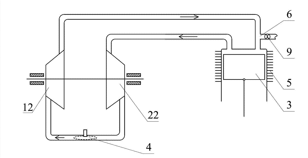
[0086] Such as figure 1 The shown heat source work heat engine includes a gas work mechanism, a gas compression mechanism, a cylinder-piston mechanism 3, an internal combustion combustion chamber 4, a working medium outlet 6 and a cooler 5, the gas work mechanism, the gas compression mechanism, the The cylinder-piston mechanism 3 is connected to form a working medium closed circuit through a communication channel, the gas working mechanism is set as a turbine power mechanism 12, and the gas compression mechanism is set as an impeller compressor 22, and the turbine power mechanism 12 and the impeller compressor The engine 22 is arranged coaxially and outputs power to the impeller compressor 22. The turbine power mechanism 12, the cylinder-piston mechanism 3 and the impeller compressor 22 are connected in turn through a communication channel, and the cooler 5 is arranged on the On the cylinder of the cylinder-piston mechanism 3, the internal combustion combustion chamber 4 is a...

Embodiment 2

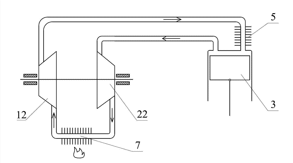
[0091] Such as figure 2 The shown heat source working heat engine includes a gas working mechanism, a gas compression mechanism, a cylinder-piston mechanism 3, a heater 7 and a cooler 5; The working medium inlet is connected, the working medium outlet of the cylinder-piston mechanism 3 is connected with the working medium inlet of the gas compression mechanism through the communication channel, and the working medium outlet of the gas compression mechanism is connected with the working medium of the gas work mechanism through the communication channel. The inlet of the substance is connected to form a closed circuit of the working medium; the gas working mechanism is set as a turbine power mechanism 12, and the gas compression mechanism is set as an impeller compressor 22, and the turbine power mechanism 12 and the impeller compressor 22 are coaxially arranged And output power to the impeller compressor 22, the cooler 5 is arranged on the communication channel between the wor...

Embodiment 3

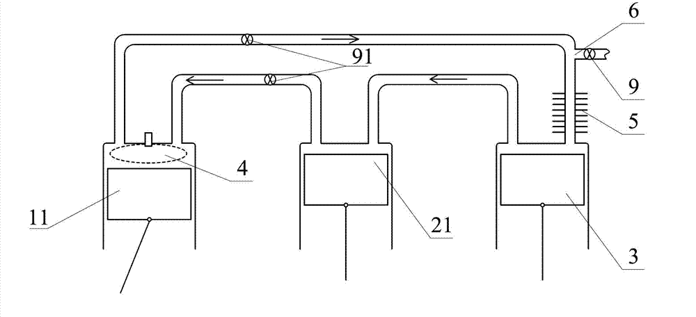
[0094] Such as image 3 The difference between the shown heat source work heater and Embodiment 1 is that the gas work mechanism is changed to a piston type gas work mechanism 11, the gas compression mechanism is changed to a piston type gas compression mechanism 21, and the internal combustion The combustion chamber 4 is relocated in the cylinder of the piston type gas work mechanism 11, and the cooler 5 is relocated on the communication channel between the working medium outlet 6 and the working medium inlet of the cylinder-piston mechanism 3, A timing control valve 91 is set on the communication passage between the working medium outlet of the piston type gas working mechanism 11 and the working medium inlet of the cylinder-piston mechanism 3, and a timing control valve 91 is set at the working medium outlet of the piston type gas compression mechanism 21. Another timing control valve 91 is provided on the communicating channel with the working medium inlet of the piston ty...


PUM


Abstract

The invention discloses a heat source working hot air engine, which comprises a gas working mechanism, a gas compression mechanism, a cylinder piston mechanism, an inner combustion chamber, a work substance outlet and a cooler, the gas compression mechanism, the gas working mechanism and the cylinder piston mechanism are sequentially communicated via a communication channel to form a work substance closed loop; the cooler is arranged on the work substance closed loop which takes the work substance of the gas working mechanism as the upstream unit and takes the cylinder piston mechanism as the downstream unit; the inner combustion chamber is arranged in the work substance closed loop which takes the work substance of the gas working mechanism as the upstream unit and takes the cylinder piston mechanism as the downstream unit. The heat source working hot air engine has a simple structure, and is high in efficiency, low in cost and long in service life.

Description

technical field [0001] The invention relates to the field of thermal energy and power, in particular to a heat engine. Background technique [0002] Traditional heat engine such as Stirling engine, the pressure of the cold cylinder and the hot cylinder are basically the same, and the compression ratio is very low (the compression ratio of the best Stirling engine in the world is only about 2), which seriously affects the The efficiency of the Stirling engine is not only that, there must be a specific phase difference between the cold cylinder and the hot cylinder, which inevitably affects its range of use. Therefore need to invent a kind of novel heat engine. Contents of the invention [0003] In order to solve the problems existing in the prior art, the technical scheme proposed by the present invention is as follows: [0004] Scheme: 1: A heat source working heat engine, comprising a gas working mechanism, a gas compressing mechanism, a cylinder piston mechanism, an in...

Claims


Application Information

Patent Timeline
Patent Type & Authority Applications(China)
IPC IPC(8): F02G1/044F02G1/055F02G1/05F02G1/057
Inventor 靳北彪
Owner ZEROQ SCI & TECH
Why Eureka
Try Eureka