Biomass fuel conveying deivce

A biomass fuel and delivery device technology, applied in fuel supply, combustion method, combustion equipment, etc., can solve the problems that powdery fuel cannot be delivered to the combustion device, the equipment structure is complicated, and the difficulty of delivery is increased, so as to achieve continuous stability The effect of fuel delivery, clean working environment and simple structure

Inactive Publication Date: 2013-07-10
邱保东
View PDF4 Cites 5 Cited by
  • Summary
  • Abstract
  • Description
  • Claims
  • Application Information

AI Technical Summary

Problems solved by technology

The above equipment has a complex structure and is suitable for long strip biomass fuel delivery devices
[0004] Biomass fuel powder with high crushing strength has low density, and it is more difficult to transport in the process of further combustion or gasification and reuse, and it is impossible to quickly transport the powdered fuel into the combustion device
If the feeding control is unstable, the problem of insufficient combustion is likely to occur, which will affect the efficiency
In the prior art, there is no powdery biomass fuel delivery device that is efficient, simple in structure, easy to operate, and conducive to full combustion. Therefore, there is a powdery biomass fuel delivery device with reasonable design, simple structure, high efficiency, and continuous stability. Conveying device, especially critical for biomass fuel combustion, gasification and reuse technology

Method used


Image

  • Biomass fuel conveying deivce

Examples


Embodiment Construction

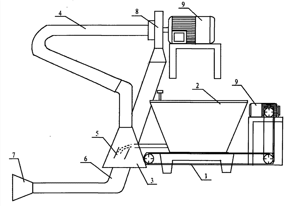
[0017] Attached below figure 1 Further explain the preferred embodiment of the biomass fuel delivery device of the present invention:

[0018] as attached figure 1 As shown in , the conveyor belt 1, the dumping funnel 2, the feeding hopper 3, the blower fan 8, and the motor 9 are used. 7. Install according to the following plan: a chain reducer is installed at one end of the conveyor belt 1, and the discharge funnel 2 is fixedly installed above the conveyor belt 1. The optimal length and width of the upper port is 1.3×0.8m, and the optimal length and width of the lower port 1.3×0.3m, the best height is 0.5m, there is a gate valve made of iron plate at the lower opening of the discharge funnel 2, the best length and width are 0.2m×0.15m, and eight gears are set according to the air flow , the gate valve can effectively save combustion fuel. The feed hopper 3 is respectively provided with a side port, an upper port and a lower port, the upper port is connected to the floating...


PUM


Abstract

The invention relates to a biomass fuel conveying deivce, in particular to a conveying deivce of powder biomass fuels. The biomass fuel conveying deivce comprises a conveying belt, a shuffling funnel, a feed hopper, a fan and a motor and is characterized by further comprising a floating dust pipe, a speed regulation plate, a conveying pipe and a material outlet. A chain speed reducer is arranged at one end of the conveying belt, the shuffling funnel is fixedly arranged above the conveying belt, and a side port, an upper port and a lower port are respectively arranged on the feed hopper. The conveying belt guides materials into the feed hopper form the side port, the upper port is connected with the floating dust pipe, and the lower port is connected with a fan port. Two ends of the floating dust pipe are connected with the upper port of the feed hopper and an air inlet of the fan respectively, and floating dust is sucked into an impeller of the fan under the negative pressure effect of the fan and is sent into a hearth through secondary conveying. A fan outlet and the speed regulation plate keep a certain distance, the conveying pipe enters a boiler through a boiler back door until to the middle of the hearth, and the conveying pipe is up with a certain inclination. A baffle is arranged at the front end of the material outlet so that fuels can be evenly jetted into the high temperature position in the boiler hearth.

Description

technical field [0001] The invention relates to a fuel conveying device, in particular to a fuel conveying device and method for biomass fuels such as straw, hay, bagasse, rice husk, sawdust and the like. Background technique [0002] Because biomass fuel is a by-product of agriculture and forestry production, it has large output and wide distribution, and is an environmentally friendly and clean renewable energy. Its high-efficiency utilization and conversion of higher-quality energy technology is the current development and utilization of renewable energy. An important direction with significant economic and environmental benefits. Specifically, the combustion and gasification of biomass materials are two important directions of development at present. Among them, based on the characteristics of long strips, uneven sizes, and easy interlacing of biomass fuels, how to provide an easy-to-manipulate, continuous Stable raw material conveying devices and methods have always be...

Claims


Application Information

Patent Timeline
Patent Type & Authority Applications(China)
IPC IPC(8): F23K3/02
Inventor 邱保东
Owner 邱保东
Why Eureka
Try Eureka