
Determination method and test device for hydraulic conductivity of structural surface

A technology of hydraulic conductivity and test equipment, which is applied in the field of determination of structural surface hydraulic conductivity and geological structural surface hydraulic conductivity. It can solve the problem of restricting the wide application of embolism tests, extremely high requirements for embolism sealing performance, and huge cost. problem, achieve the effect of shortening the test time, reducing the work intensity and improving the test efficiency

Active Publication Date: 2016-04-06
NANJING UNIV
View PDF7 Cites 0 Cited by
  • Summary
  • Abstract
  • Description
  • Claims
  • Application Information

AI Technical Summary

Problems solved by technology

[0004] The technical problem to be solved by the present invention is: the existing in-situ test can only obtain the overall seepage parameters of all structural surfaces in the pressurized water section of the borehole, and does not aim at a single structural surface, so the quantification of the seepage characteristics of a single and intersecting structural surface has not been solved Difficulties in characterization, and the existing in-situ test tests have extremely high requirements on the sealing performance of embolism, which makes the manufacturing process of the whole set of equipment complicated, the operation process is cumbersome, and the cost is huge, which limits the large-scale popularization and application of embolism tests.

Method used


Image

  • Determination method and test device for hydraulic conductivity of structural surface
  • Determination method and test device for hydraulic conductivity of structural surface
  • Determination method and test device for hydraulic conductivity of structural surface

Examples


Embodiment Construction

[0034] In order to make the content of the present invention more obvious and understandable, the following in conjunction with the attached figure 1 - attached Figure 7 and specific implementation methods for further description.

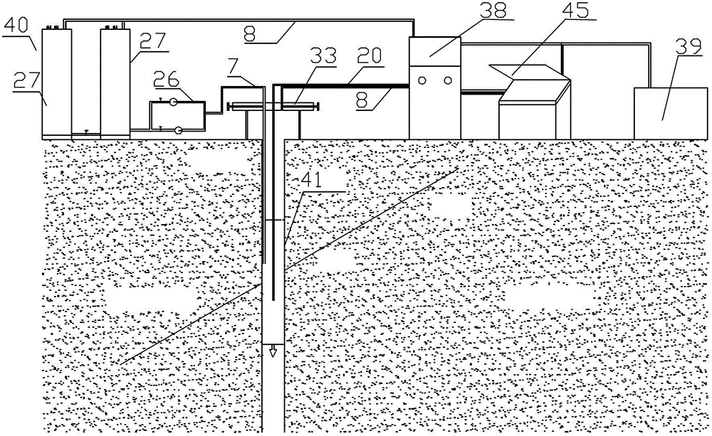
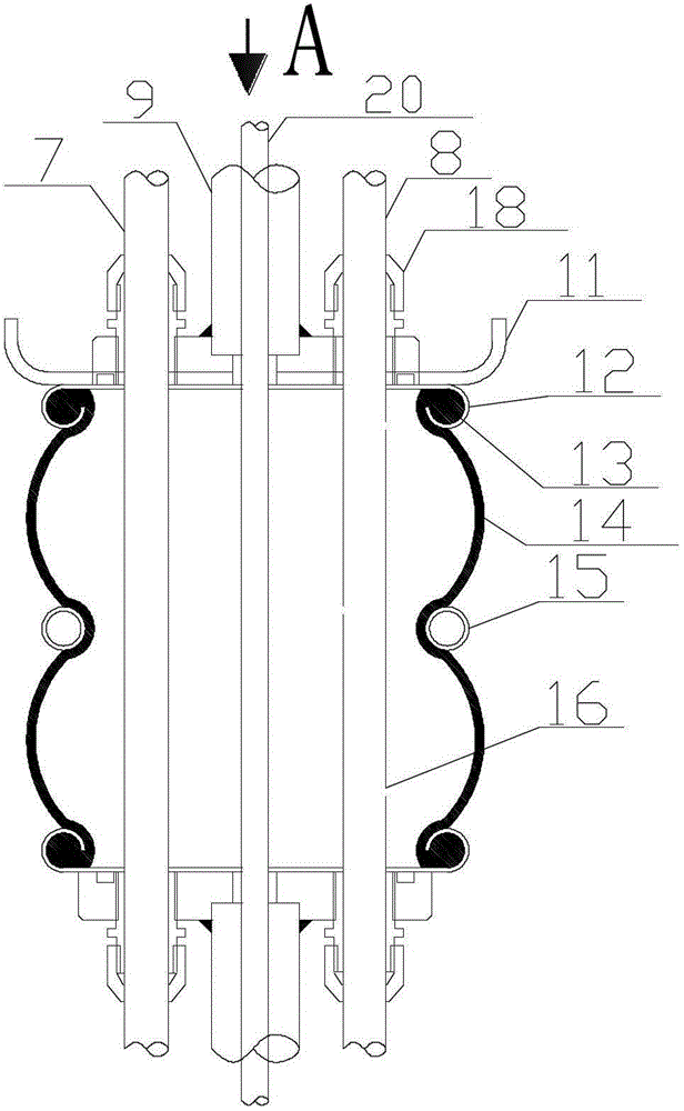
[0035] figure 1 It is the structural arrangement diagram of the present invention, such as figure 1 As shown, the structural surface hydraulic conductivity test device of the present invention includes two water vapor exchange chambers 27 , a host system 38 , a power supply system (power supply) 39 , a plugging system 41 , a support 33 and a processing device 45 . The power supply supplies power to the host system 38, the water vapor exchange chamber 27 and the plugging system 41, the water vapor exchange chamber 27 supplies water to the plugging system 41, and the plugging system 41 extends into the geological structure plane for measurement and transmits the measured data to the host computer In the system 38 , the support 33 is arranged abov...


PUM


Abstract

The invention aims to solve the technical problems that the existing in-situ test experiment can only acquire the total permeability parameters of all structural planes of a drilling pressurized-water section, and does not refer to a single structural plane, therefore, the difficulty of permeability characteristic quantitative characterization of single and crossed structural plane is not solved, the existing in-situ test experiment requires extremely high seal performance of a bolt plug, and thus the whole equipment is complex in manufacturing technology and operation flow, is high in cost capital consumption, and restricts the wide-range popularization of the bolt plug test and the like. The technical scheme adopted by the invention is that a structural plane transmission coefficient test device comprises a host machine system, a power supply system, a water supply system and a sealing system; the power supply system supplies power for the host machine system, the water supply system and the sealing system; the water supply system supplies water for the sealing system; the sealing system extends into a geological structure plane to measure, and transmits the measured data to the host machine system.

Description

technical field [0001] The present invention relates to a structural surface hydraulic conductivity test device, especially a device that can be used for the in-situ measurement of the permeability parameters of many geological structural surfaces such as rock mass fissures (single, multiple, crossed), joint-intensive areas, fault fracture zones, etc. At the same time, it is a structural surface hydraulic conductivity test device suitable for measuring the permeability parameters of geological materials such as cohesive soil, sandy soil, gravel and concrete; the present invention also relates to a method for determining the structural surface hydraulic conductivity, especially a method that can be used for In situ measurement of permeability parameters of rock mass fissures (single, multiple, crossed), joint-intensive areas, fault fracture zones, etc. Method for determination of hydraulic transmissivity of geological structural surface by parameter measurement. Background te...

Claims


Application Information

Patent Timeline
Patent Type & Authority Patents(China)
IPC IPC(8): G01N13/04
Inventor 李晓昭付安学郭亮章杨松
Owner NANJING UNIV
Learn More