Equalized current output circuit of insulated gate bipolar transistor

A bipolar transistor and output circuit technology, applied in the field of IGBT parallel current sharing circuit, can solve the problems of uneven current, different saturation voltage drop parameters, etc., and achieve the effect of fast adjustment speed, process compatibility and easy portability

Inactive Publication Date: 2013-07-10
UNIV OF ELECTRONICS SCI & TECH OF CHINA +1
View PDF7 Cites 17 Cited by
  • Summary
  • Abstract
  • Description
  • Claims
  • Application Information

AI Technical Summary

Problems solved by technology

[0004] The technical problem to be solved by the present invention is to provide an insulated gate bipolar transistor current sharing output circuit to solve

Method used


Image

  • Equalized current output circuit of insulated gate bipolar transistor
  • Equalized current output circuit of insulated gate bipolar transistor
  • Equalized current output circuit of insulated gate bipolar transistor

Examples


Embodiment 1

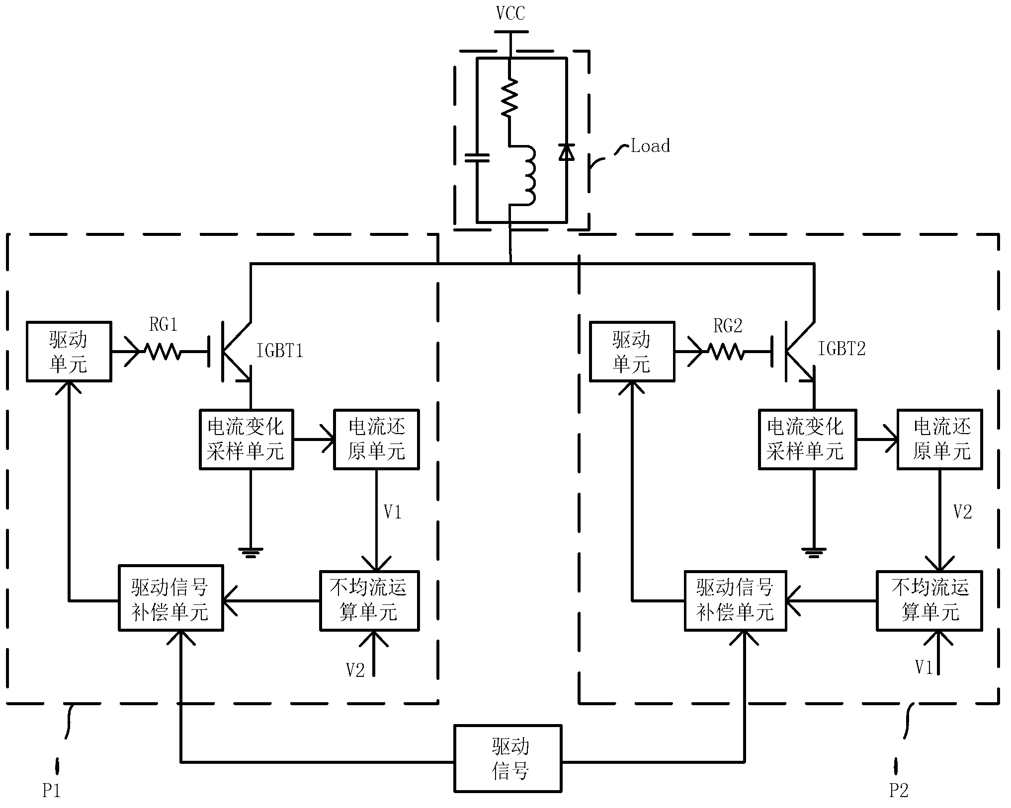
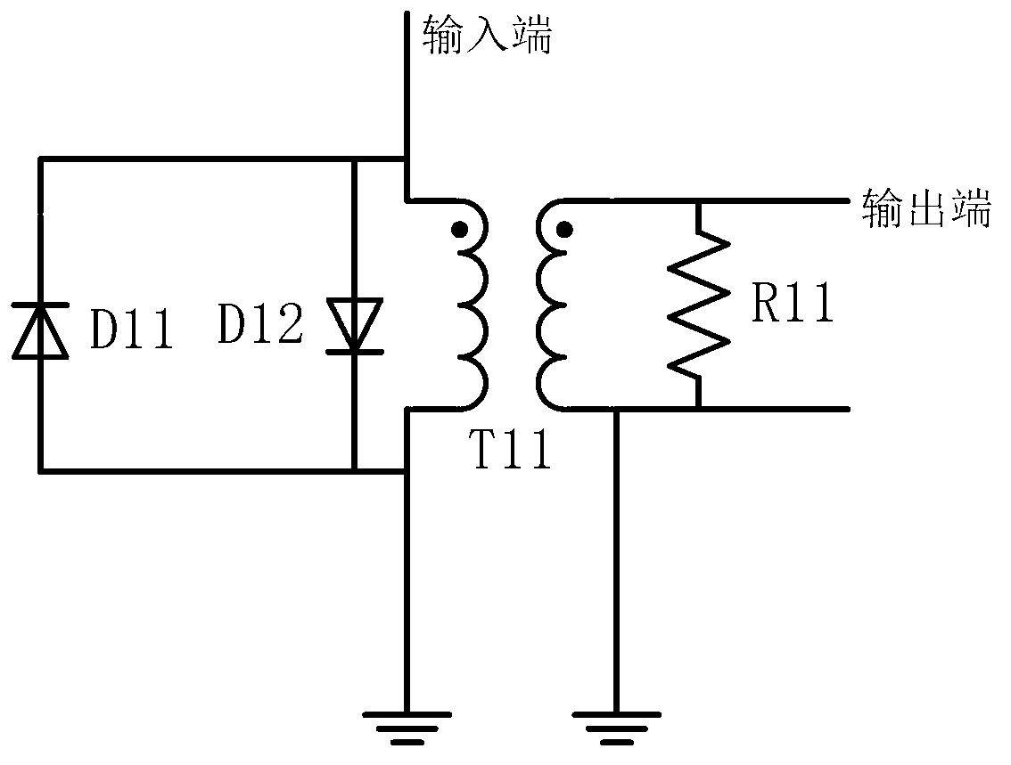
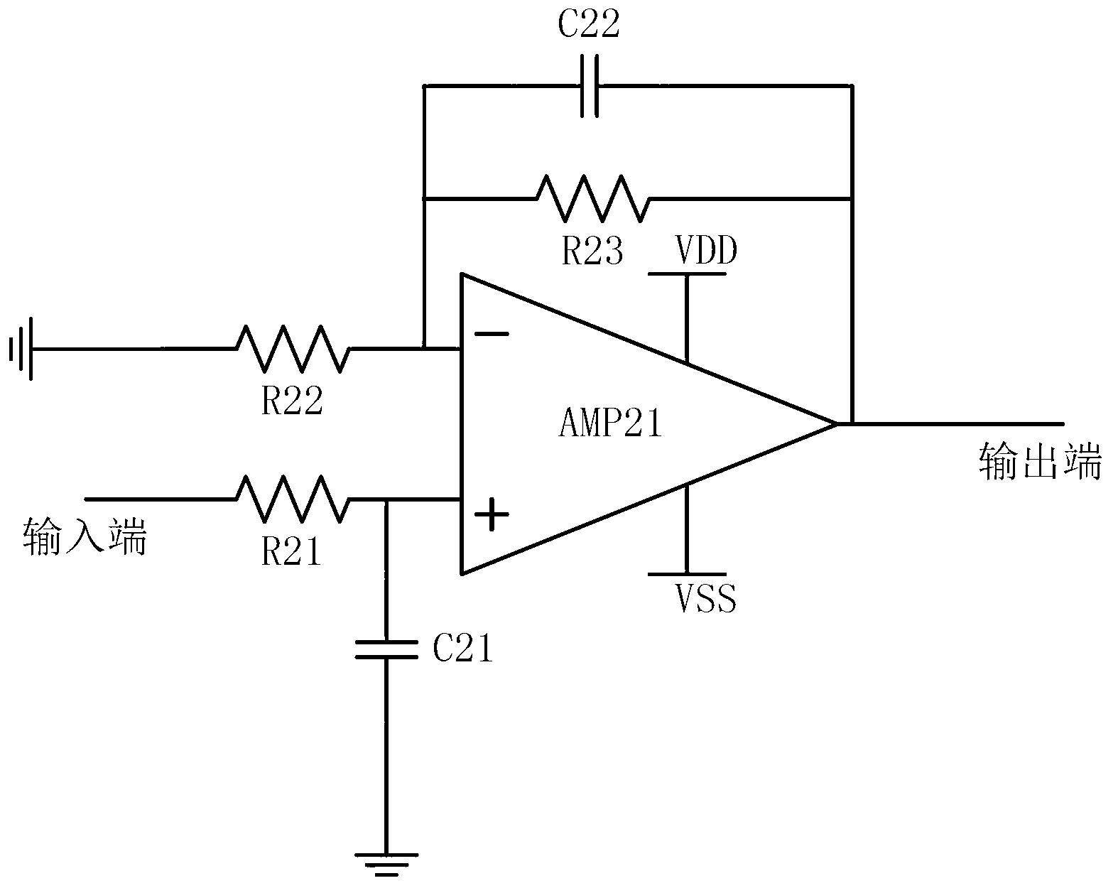
[0024] The circuit structure of this example is as figure 1 As shown, it consists of modules P1 and P2 connected in parallel, corresponding to the case of N=2. The power supply VCC is connected to the modules P1 and P2 through the load Load, and each module specifically includes: a current change sampling unit, a current restoration unit, an uneven current calculation unit, a drive signal compensation unit, a drive unit and an IGBT device. Wherein, IGBT1 and IGBT2 are two IGBT devices with inconsistent electrical characteristics. When the driving signal arrives, the electrical characteristics of each IGBT are inconsistent, which will lead to uneven current flow when the IGBT is turned on. The weak uneven current will be detected by the current change sampling unit of this module and transmitted to the current of this module in the form of voltage. The reduction unit obtains a voltage value proportional to the current value through the integral processing of the current reduct...

Embodiment 2

[0033] Such as Figure 7 As shown, it is a schematic diagram of an IGBT current sharing circuit composed of N (≥ 3) modules connected in parallel in P1, P2...PN, and the output terminal voltage V of the uneven current calculation unit of a certain module xin , is the output voltage V of the current reduction unit of this module X The difference between the average value of the output voltage of the current reduction unit of other modules, that is For the specific structure of each module, refer to the description of Embodiment 1, which is omitted here.

[0034] Taking the experimental data of three IGBT parallel output circuits as an example, when there is no current sharing measure, the conduction currents are 12.415A, 11.248A, and 9.3536A, the average output current of the three IGBTs is 11.0055A, and the maximum current difference is 3.0614A. After adopting the technology of the present invention for current sharing control, the conduction currents of the three IGBTs are...


PUM


Abstract

The invention relates to a parallel equalized current circuit of an IGBT (insulated gate bipolar transistor), and in particular relates to an equalized current output circuit of an insulated gate bipolar transistor to solve the problem of uneven current caused by inconsistent electrical characteristics particularly saturation voltage drop parameters of the IGBT. The technical scheme of the invention is as follows: the equalized current output circuit of the insulated gate bipolar transistor consists of N modules connected in parallel, wherein N is an integer and is more than or equal to 2; and each module comprises a current change sampling unit, a current reduction unit, an uneven current arithmetic unit, a driving signal compensation unit, a driving unit and an IGBT. The equalized current output circuit of the insulated gate bipolar transistor can be used for performing dynamic current equalization and static current equalization parallelly on IGBTs with different electrical characteristics, and is particularly suitable for performing parallel current equalization on the IGBTs of which the electrical characteristics are greatly different, therefore, the equalized current output circuit has universality.

Description

technical field [0001] The invention relates to insulated gate bipolar transistor (IGBT) technology, in particular to an IGBT parallel current sharing circuit. Background technique [0002] IGBT is a high-voltage high-power device, often used as a switching device in high-power power electronic equipment. In order to expand the output capacity of power electronic devices, when the capacity of a single main switching device does not meet the power requirements, IGBTs are used in parallel to increase the maximum current allowed by the device. When IGBT modules are used in parallel, only when each single power module reaches an ideal symmetrical state both statically (forward conduction operation) and dynamically (such as switching process), can the paralleled IGBT modules be used to the greatest extent. However, factors such as unbalanced electrical characteristics of IGBT devices, asynchronous drive signals, and unbalanced circuit parasitic parameters will cause current imba...

Claims


Application Information

Patent Timeline
IPC IPC(8): H02M1/088
Inventor 李泽宏吴明进刘广涛蒋汇曾智
Owner UNIV OF ELECTRONICS SCI & TECH OF CHINA
Why Eureka
Try Eureka