Non-isolated bidirectional multiport direct current (DC) converter

A DC converter and multi-port technology, applied in the direction of conversion equipment without intermediate conversion to AC, can solve the problems of lowering system reliability, lowering system efficiency, and low power conversion efficiency, so as to improve system reliability and improve system efficiency. The effect of efficiency and adaptability

Inactive Publication Date: 2013-07-10
NANJING UNIV OF AERONAUTICS & ASTRONAUTICS
View PDF2 Cites 6 Cited by
  • Summary
  • Abstract
  • Description
  • Claims
  • Application Information

AI Technical Summary

Problems solved by technology

[0003] (1) The power transmission between each input source must go through two-stage power conversion, which reduces the system efficiency;
[0004] (2) The setting of the common DC bus voltage should take into account the limit conditions of each input source, with the figure 1 For example, step-down conversion is used between each input source and the common DC bus. In order to ensure the controllable power of the system, the voltage value of the common DC bus must be lower than the voltage of all input sources. For the step-down converter, the input and output The greater the voltage difference between them, the lower the power conversion efficiency;
[0005] (3) In order to ensure the stability of the public DC bus voltage, a large-capacity capacitor needs to be installed on the public DC bus, which greatly increases the volume, weight and cost of the system. Moreover, once the capacitor has a short circuit or other fault, it will cause accidents such as fire and cause system failure. failure of
[0006] (4) The introduction of common DC bus capacitors makes any two bidirectional DC converters form a parallel or cascaded structure. The stability design of the cascaded system is complicated, which increases the difficulty of system implementation and reduces the reliability of the system.

Method used


Image

  • Non-isolated bidirectional multiport direct current (DC) converter
  • Non-isolated bidirectional multiport direct current (DC) converter
  • Non-isolated bidirectional multiport direct current (DC) converter

Examples


Embodiment Construction

[0019] The present invention will be further described below in conjunction with accompanying drawing.

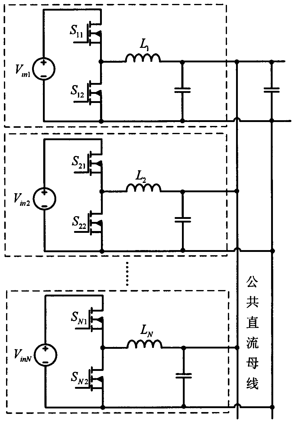
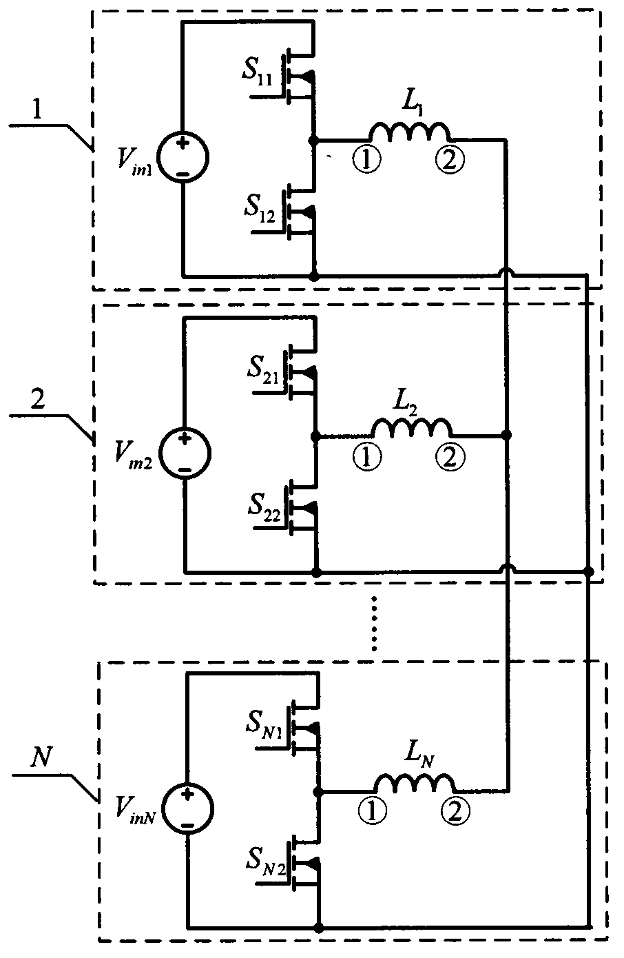
[0020] as attached figure 1 As shown, the converter is composed of N bidirectional input / output circuit units, N is a natural number greater than 1, wherein: each bidirectional input / output circuit unit is composed of an input source, a first switch tube, a second switch tube Composed of an inductor, the positive pole of the input source is connected to the drain of the first switching tube, the negative pole of the input source is connected to the source of the second switching tube, and the source of the first switching tube is connected to the drain of the second switching tube and the inductor ① terminal, the ② terminals of each inductor in the N bidirectional input / output circuit units are connected together, and the negative terminals of each input source in the N bidirectional input / output circuit units are connected together.

[0021] The following takes a non-isol...


PUM


Abstract

The invention relates to a non-isolated bidirectional multiport direct current (DC) converter, and belongs to the technical field of power electronic converters. The converter is formed by N bidirectional input/output circuit units, wherein the N is a natural number bigger than 1. Each bidirectional input/output circuit unit is formed by an input source, two switching tubes and an inductor, the input sources of all the bidirectional input/output circuit units are in public ground connection, and one ends of the inductors of all the bidirectional input/output circuit units are connected together. The non-isolated bidirectional multiport DC converter has the advantages that all the input sources are in public ground connection, single-stage non-isolated switching is carried out among all the input sources, voltage ascending and descending switching is carried out among all the input sources, power can be transmitted mutually among all the input sources, a circuit topology is simple, power density is high, a switching rate is high, reliability is high, cost is low and the like, and the non-isolated bidirectional multiport DC converter settles key technology for a distributed DC supply system.

Description

technical field [0001] The invention relates to a non-isolated bidirectional multi-port DC converter, which belongs to the technical field of power electronic converters. Background technique [0002] In DC distributed power supply systems such as renewable energy power supply systems and aerospace power supply systems, there are usually multiple DC buses or input sources with similar voltage levels. In order to improve the reliability of the entire power supply system, it is necessary to connect each DC bus or input sources to each other. , in order to realize mutual bidirectional, controllable power transmission. In order to realize the connection of multiple DC buses or input sources, traditional solutions usually adopt a system architecture based on a common DC bus, as shown in the attached figure 1 As shown, each DC bus or input source is connected to the common DC bus through a bidirectional DC converter, and the public DC bus is used as a medium to complete the power...

Claims


Application Information

Patent Timeline
Patent Type & Authority Applications(China)
IPC IPC(8): H02M3/10
Inventor 吴红飞张君君许鹏邢岩秦晓晴
Owner NANJING UNIV OF AERONAUTICS & ASTRONAUTICS
Why Eureka
Try Eureka