Loop heat pipe cooling device with pool boiling function

A technology of heat dissipation device and loop heat pipe, which is applied in the direction of cooling/ventilation/heating transformation, etc., can solve the problems of limited heat dissipation capacity of flat-plate loop heat pipe, difficult heat transfer outside the system, and unfavorable performance of electronic devices, so as to increase and strengthen the The effect of heat exchange area, high heat transfer efficiency and basic temperature

Inactive Publication Date: 2013-07-10
XI AN JIAOTONG UNIV
View PDF5 Cites 21 Cited by
  • Summary
  • Abstract
  • Description
  • Claims
  • Application Information

AI Technical Summary

Problems solved by technology

[0004] 1. Electronic components are immersed in a static working fluid for heat exchange, and the critical heat flux value is low, so it is necessary to increase the degree of supercooling to increase the critical heat flux density
[0005] 2. Although the square column microstructure can transfer the heat of electronic components to the liquid in the pool in a timely and effective manner, since the system has no power, it is difficult to export this part of the heat out of the system to maintain the temperature of the liquid in the pool
[0006] 3. When cooling the liquid in the pool, an additional heat dissipation system is required, and the structure is complex
[0010] However, the heat dissipation capacity of the flat-plate loop heat pipe is limited, there is a lot of heat leakage from the back, and the temperature fluctuation is often large, especially when the power is low, which is not conducive to the stable performance of electronic devices.
In addition, there are two main ways to arrange the compensator, one is located on the upper part of the capillary core, increasing the liquid storage capacity by increasing the height; the other is placed on the side of the steam channel, increasing the liquid storage capacity by increasing the length and width, both Not suitable for small space applications

Method used


Image

  • Loop heat pipe cooling device with pool boiling function
  • Loop heat pipe cooling device with pool boiling function
  • Loop heat pipe cooling device with pool boiling function

Examples


Embodiment Construction

[0032] The present invention will be further described in detail below in conjunction with the drawings:

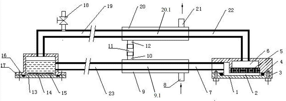
[0033] See figure 1 , The loop heat pipe heat dissipation device with pool boiling of the present invention includes a flat plate evaporator 1, a first condenser 9, a pool boiling evaporator 13, and a second condenser 20; the uppermost metal cavity of the flat evaporator 1 Equipped with a compensator 6; the outlet of the flat plate evaporator 1 is connected to the outlet of the pool boiling evaporator 13 through a first connecting pipe; the first condenser 9 is a sleeve type and is sleeved on the first connecting pipe; the pool boiling evaporator The outlet of 13 is connected to the compensator 6 through a second connecting pipe, and the second condenser 20 is also a sleeve type and is sleeved on the second connecting pipe; the condensate outlet 10 of the first condenser 9 is connected to the second condenser through a pipe The condensate inlet 12 of 20 is connected.

[0034]...


PUM


Abstract

The invention discloses a loop heat pipe cooling device with a pool boiling function. The loop heat pipe cooling device comprises a flat plate type evaporator, a first condenser, a pool boiling evaporator and a second condenser, wherein a compensator is arranged on the top most portion of a metal cavity of the flat plate type evaporator, and an outlet of the flat plate type evaporator is connected to an outlet of the pool boiling evaporator through a first connecting pipeline. The first condenser is a casing pipe type condenser and is mounted on the first connecting pipeline in a sleeved mode. The outlet of the pool boiling evaporator is connected with the compensator through a second connecting pipeline. The second condenser is also a casing pipe type condenser and is mounted on the second connecting pipeline in a sleeved mode. A condensate outlet of the first condenser is connected with a condensate inlet of the second condenser through a pipeline. The loop heat pipe cooling device with the pool boiling function fully combines the advantages of a square column microstructural pool boiling device, wherein the advantages includes that the heat dissipation efficiency is high, the temperature fluctuation is small, the occupied space is small, and a loop heat pipe can be used for long-distance transmission; capillary suction force generated by a capillary core is used for providing motive power for a system; and the effect that electronic parts and components can be cooled high efficiently is guaranteed.

Description

Technical field [0001] The invention belongs to the technical field of cooling and heat dissipation of electronic components, and relates to a heat dissipation device, in particular a loop heat pipe heat dissipation device with pool boiling. Background technique [0002] With the development of high integration, high power and miniaturization of electronic components, the problem of heat treatment of electronic components has become more and more severe. How to effectively conduct heat in time has become an important factor restricting the development of electronic components. Cooling technologies such as air-cooling can no longer meet the requirements of its high heat dissipation rate. [0003] The use of liquid to cool electronic components is an efficient way to dissipate heat, especially the electronic components are directly immersed in a small pool filled with non-conductive liquid, and the phase change heat transfer of the pool boiling device is used to cool them. In order ...

Claims


Application Information

Patent Timeline
Patent Type & Authority Applications(China)
IPC IPC(8): H05K7/20
Inventor 魏进家吕虓龙延
Owner XI AN JIAOTONG UNIV
Why Eureka
Try Eureka