Supercharge Your Innovation With Domain-Expert AI Agents!

Cooling device for hot-rolled steel strip

A technology of cooling device and steel strip, which is applied in the direction of workpiece cooling device, quenching device, guiding/positioning/aligning device, etc., can solve the problems of high cost, no installation, large-scale device, etc., and achieve low cost and high manufacturing Effect

Active Publication Date: 2015-11-25
PRIMETALS TECHNOLOGIES JAPAN LTD +1
View PDF10 Cites 0 Cited by
  • Summary
  • Abstract
  • Description
  • Claims
  • Application Information

AI Technical Summary

Problems solved by technology

[0019] However, in the above-mentioned conventional cooling device, either the cooling capacity is insufficient or the cost is high because of the large size of the device, therefore, it cannot be realized as a device for manufacturing a hot-rolled steel strip composed of a fine grain structure.
[0020] That is, in the cooling device of Patent Document 1, a non-cooling area in which measuring equipment is arranged is provided between the first cooling device and the second cooling device. above) and it is necessary to arrange a plurality of nozzles near the output side of the work roll, and it is necessary to provide a guide with a guide surface, but there is no description about the guide
[0021] In addition, in the cooling device of Patent Document 2, since a plurality of cooling units are arranged in the conveying direction, it is not cooling immediately after rolling, but the rolls are arranged at about 1.1 to 1.3 times the roll diameter. There are enough nozzles, so the cooling rate cannot be obtained sufficiently, so it cannot be applied to the device for manufacturing hot-rolled steel strip composed of fine-grained structure.
[0022] In addition, in the cooling device of Patent Document 3, the rolling material cooling nozzle is arranged on the output side of the workpiece roll, but the spray hole for directly spraying cooling water on the rolling material to cool the rolling material is not provided on the wiper. Therefore, In the lower part (or upper part) of the part where the wiper is installed, there is an area where the rolled product cannot be cooled, so that the cooling rate cannot be realized sufficiently

Method used


Image

  • Cooling device for hot-rolled steel strip
  • Cooling device for hot-rolled steel strip
  • Cooling device for hot-rolled steel strip

Examples


Embodiment 1

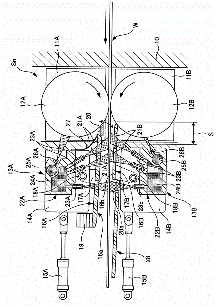
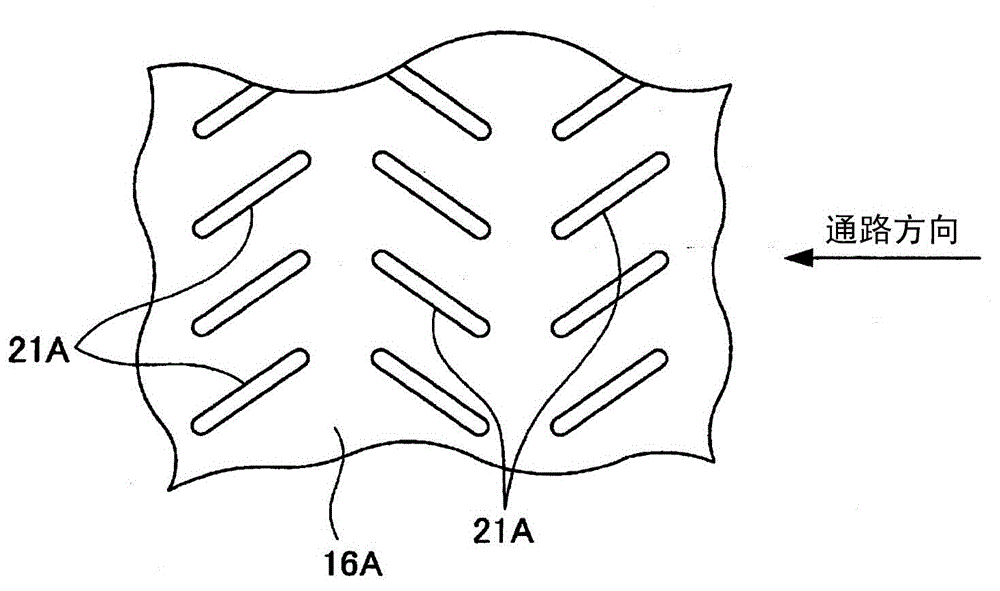
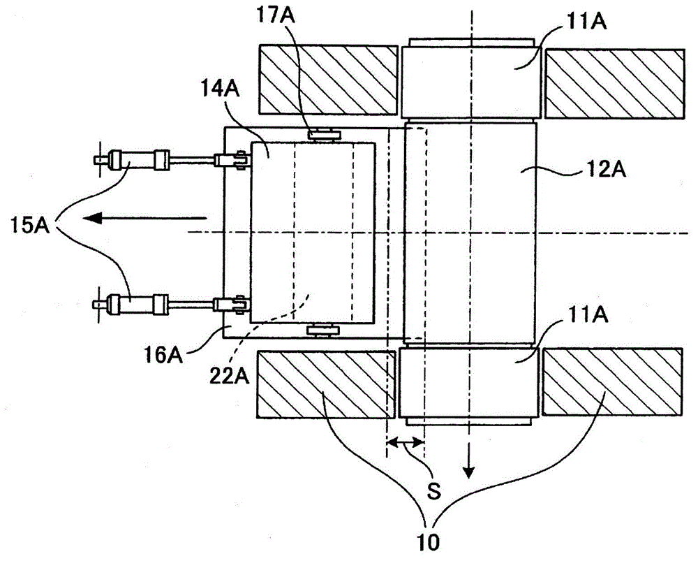
[0055] figure 1 is a side sectional view showing a cooling device for a hot-rolled steel strip according to Embodiment 1 of the present invention, figure 2 is the top view of the upper guide, Figure 3A is a plan view of the upper guide during rolling, Figure 3B It is a plan view when the roller of the upper guide is replaced.

[0056] Such as figure 1 As shown, in the final stand Sn on the finishing mill row of the hot rolling equipment, the upper cooling device 13A and the upper cooling device 13A and The lower cooling device 13B, the upper work roll 12A is rotatably supported with respect to the casing 10 via a pair of left and right upper work roll chucks 11A via a motor not shown, and the lower work roll 12B is similarly provided via a pair of left and right The lower work roll chuck 11B is rotatably supported with respect to the housing 10 by a motor not shown.

[0057] In addition, as described later Figure 3B As shown, the upper and lower work rolls 12A, 12B a...

Embodiment 2

[0085] Figure 4 is a side sectional view showing a cooling device for a hot-rolled steel strip according to Example 2 of the present invention, Figure 5A is the top view of non-cross rolling, Figure 5B It is a plan view at the time of cross rolling.

[0086] This is an example in which the upper and lower cooling devices 13A and 13B in the first embodiment are applied to a cross rolling mill in which the upper and lower work rolls 12A and 12B intersect in the direction in which the rolled product W is conveyed.

[0087] Specifically, a pair of left and right hydraulic cylinders 15A, 15B above and below the rolled material W are pin-coupled to the nozzle blocks 14A, 14B and the casing 10 so that they can rotate horizontally at the front end of the piston rod and the base end of the head. , and spacers 30A, 30B abutting against the upper and lower workpiece roll chucks 11A, 11B are attached to the left and right front sides of the nozzle blocks 14A, 14B via brackets 29 . T...


PUM

PropertyMeasurementUnit
crystal sizeaaaaaaaaaa

Abstract

Provided is a cooling system for a hot-rolled steel strip capable of increasing the cooling rate for rapidly cooling a rolled steel immediately after rolling and suitable for an apparatus for manufacturing a hot-rolled steel strip having a fine-grained structure. For this purpose, guides (16A, 16B) having guiding surfaces (16a, 16b) to guide a rolled steel (W) exiting work rolls (12A, 12B) in the conveyance direction are provided at exits of the work rolls in a final stand (Sn) of a finish rolling mill line in a manner that the guides can follow a change in the diameter of the work rolls, a number of injection holes (21A, 21B) are formed in the guides, and a number of rolled steel cooling nozzles (23A, 23B) are provided to spray a large amount of cooling water through the injection holes directly onto the rolled steel.

Description

technical field [0001] The present invention relates to a cooling device for a hot-rolled steel strip, and more specifically, to a hot-rolled steel strip suitable for producing a ferrite structure with a fine-grained grain size of, for example, 3 to 4 μm or less. cooling device in the device. Background technique [0002] As a cooling device for a hot-rolled steel strip, there are devices disclosed in Patent Documents 1 to 3, for example. That is, Patent Document 1 describes a device in which the first cooling device installed immediately behind the final stand in the finishing mill row of the hot rolling facility is equipped with a cooling device for forming a strip shape or an ellipse shape on the surface to be cooled of the steel plate. The nozzles in the jet collision area and the barrier rollers used to block the cooling water sprayed from the nozzles are formed with a water storage tank for cooling water in the area between the rollers of the final stand and the barri...

Claims


Application Information

Patent Timeline
Patent Type & Authority Patents(China)
IPC IPC(8): B21B45/02B21B13/14B21B27/10B21B39/14B21B39/16
CPCC21D1/667B21B39/16B21B45/0218B21B45/0233B21B2027/103B21B13/14B21B27/10B21B39/14B21B45/02
Inventor 松本浩一池本裕二原口洋一小林一晓
Owner PRIMETALS TECHNOLOGIES JAPAN LTD
Features
  • R&D
  • Intellectual Property
  • Life Sciences
  • Materials
  • Tech Scout
  • Unparalleled Data Quality
  • Higher Quality Content
  • 60% Fewer Hallucinations
Learn More