Tube for heat exchanger

A technology of heat exchanger and heat exchange medium, which is used in heat exchanger fixing, heat exchange equipment, indirect heat exchanger, etc., can solve the problems of unstable brazing performance of flat tubes, and achieve the effect of improving brazing performance

Inactive Publication Date: 2013-07-10
DENSO CORP
View PDF6 Cites 6 Cited by
  • Summary
  • Abstract
  • Description
  • Claims
  • Application Information

AI Technical Summary

Problems solved by technology

Therefore, the brazing performance of flat tubes may be unstable in some cases

Method used


Image

  • Tube for heat exchanger
  • Tube for heat exchanger
  • Tube for heat exchanger

Examples


no. 1 example

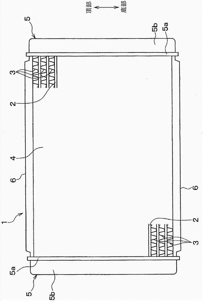
[0035] The following will be based on Figure 1-7 The first embodiment of the present invention is described. figure 1 It is a front view of the radiator 1 according to this embodiment.

[0036] In this embodiment, the flat tube (tube for heat exchanger) 2 is applied for exchanging heat between engine cooling water (heat exchange medium) and air (atmosphere) for cooling the vehicle engine (internal combustion engine) 的radiator 1.

[0037] figure 1 The flat tube 2 in is the tube through which engine cooling water flows. The flat tube 2 is formed into a flat shape so that the direction of air flow (perpendicular to figure 1 The direction of the paper plane) is aligned with the long radius direction. Further, a plurality of flat tubes 2 along figure 1 The vertical directions are arranged parallel to each other, so that the longitudinal direction of the flat tube and figure 1 Align in the horizontal direction. A detailed description of the flat tube 2 is provided later.

[0038] Outer ...

no. 2 example

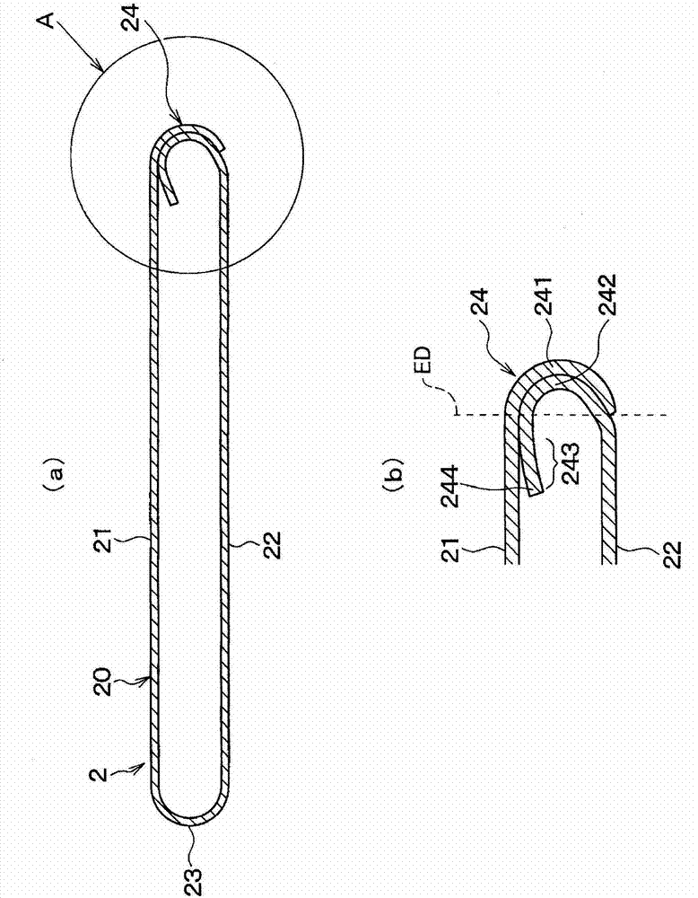
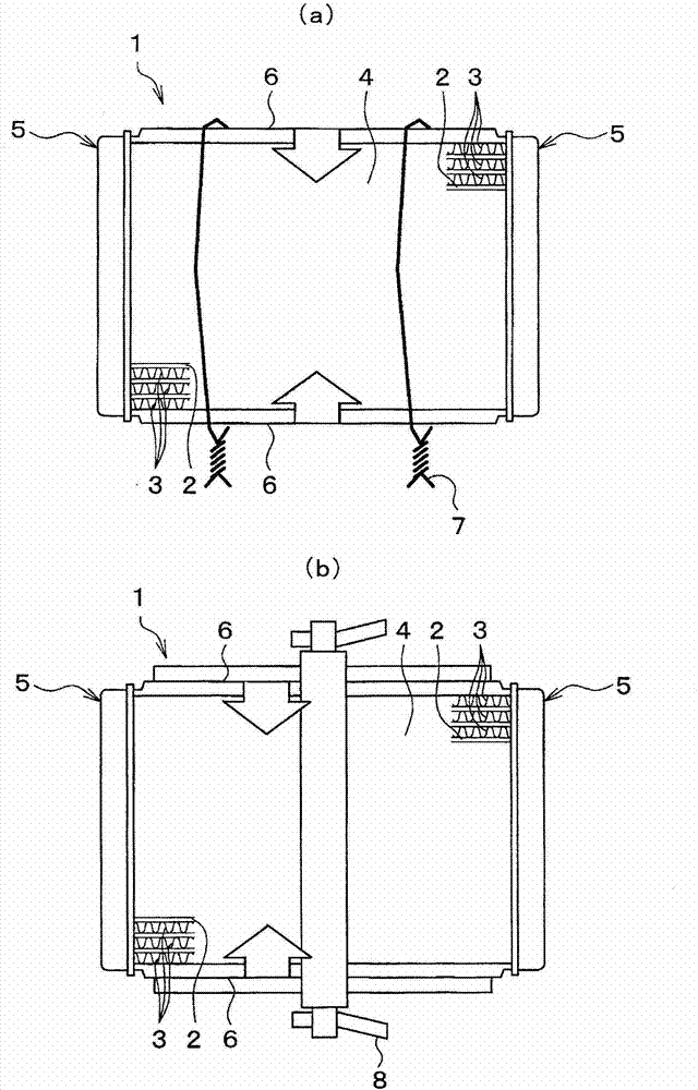
[0063] Next, based on Figure 8 (a) and Figure 8 (b) The second embodiment of this embodiment is described. Here, Figure 8 (a) and Figure 8 (b) is a cross-sectional view showing the cross section of the flow passage of the flat tube 2 of this embodiment. Figure 8 (a) shows the entire flow passage section of the flat tube 2, and Figure 8 (b) shows Figure 8 A partial enlarged view of part B in (a). In this embodiment, descriptions of components similar or equivalent to those in the first embodiment will be omitted or simplified.

[0064] The flat tube 2 of this embodiment has an extension portion 243 in which the inner wall portion 242 extends from a portion opposite to the outer wall portion 241 to the first curved portion 23. In the extension portion 243, the portion (radiating fin portion 243a) opposed to the respective flat plate portions 21, 22 in the short radius direction of the flat tube 2 is formed in a corrugated shape to serve as an inner radiating fin for increasi...


PUM


Abstract

A tubular member (20) that constitutes a tube for a heat exchanger comprises a pair of flat sections (21, 22) that are aligned in parallel so as to face one another in the short-axis direction of the channel cross section, and a pair of curved sections (23, 24) that face one another in the long-axis direction of the channel cross section and connect the pair of flat sections (21, 22) to one another. One of the curved sections (23, 24) constitutes a joint part at which an outer wall portion (241), which extends from an end of the pair of flat sections (21, 22) and constitutes a part of the outer wall of the tubular member (20), and an inner wall portion (242), which extends from an end of the pair of flat sections (21, 22) and constitutes a part of the inner wall of the tubular member (20), overlap and are joined by brazing. The inner wall portion (242) is joined in a manner such that the portion facing the outer wall (241) is closely adhered thereto, and the leading end (244) facing the flat section (21) is spaced apart from the flat section (21).

Description

[0001] Cross references to related applications [0002] This application is based on the Japanese Patent Application (2010-252807) filed on November 11, 2010, and the content of the application is incorporated herein by reference in its entirety. Technical field [0003] The present invention relates to a tube for a heat exchanger, and the tube can be usefully applied to a radiator such as an automobile. Background technique [0004] A flat tube formed by bending a plate-shaped member (for example, a metal plate) has been known as a tube for a heat exchanger. These flat tubes and corrugated fins are alternately stacked on each other to thereby form a heat exchange core, and a header tank and pipes for introducing a heat exchange medium are coupled to the heat exchange core, thereby constructing a heat exchanger. [0005] This flat tube is formed as follows: a pair of flat plate portions facing each other with a given gap in the short radius direction between the pair of flat plate p...

Claims


Application Information

Patent Timeline
Patent Type & Authority Applications(China)
IPC IPC(8): F28F1/02B21D53/04F28D1/053F28F1/40
CPCB21C37/14B21C37/151F28D1/0391B23K1/0012F28D1/05366F28D2021/0094F28F2275/04F28F3/086
Inventor 大原贵英浜田浩吉田典生榊原哲哉光川一浩王宇现田启之齐藤充克中坊正宫崎典幸马场则昌岛贯宏泰
Owner DENSO CORP
Why Eureka
Try Eureka