Large-size high-speed micropore drilling system

A large-format, micro-hole technology, used in welding equipment, laser welding equipment, metal processing equipment, etc., can solve the problems of poor control of fine processing and poor control of laser beam modulation trajectory, and achieve rich spatial trajectory modulation motion, Improve efficiency and drilling quality, improve the effect of scanning processing format

Active Publication Date: 2013-07-17
张立国
View PDF5 Cites 15 Cited by
  • Summary
  • Abstract
  • Description
  • Claims
  • Application Information

AI Technical Summary

Problems solved by technology

[0004] The application number is 200380110303.9. There is no problem with the galvanometer used to switch the laser focus. However, the circular modulation movement of the beam in front of the galvanometer uses a reflective lens to reflect and modulate the laser to make a circular motion. The disadvantage is that the laser is a cone. Shaped rotation movement, especially when two or more mirrors are used in combination, and when the distance between the mirrors is slightly larger, the laser beam is reflected back and forth, and the modulation trajectory of the laser beam is very difficult to control, which is not good for fine processing. Control, this method is not ideal for high-speed and high-precision drilling of small apertures below 100 microns, and because the reflective scanning trajectory of the mirror to the beam is a spatial conical shape, the small hole drilled is an inverted tapered hole. form should be avoided in practice

Method used


Image

  • Large-size high-speed micropore drilling system
  • Large-size high-speed micropore drilling system

Examples


Embodiment 1

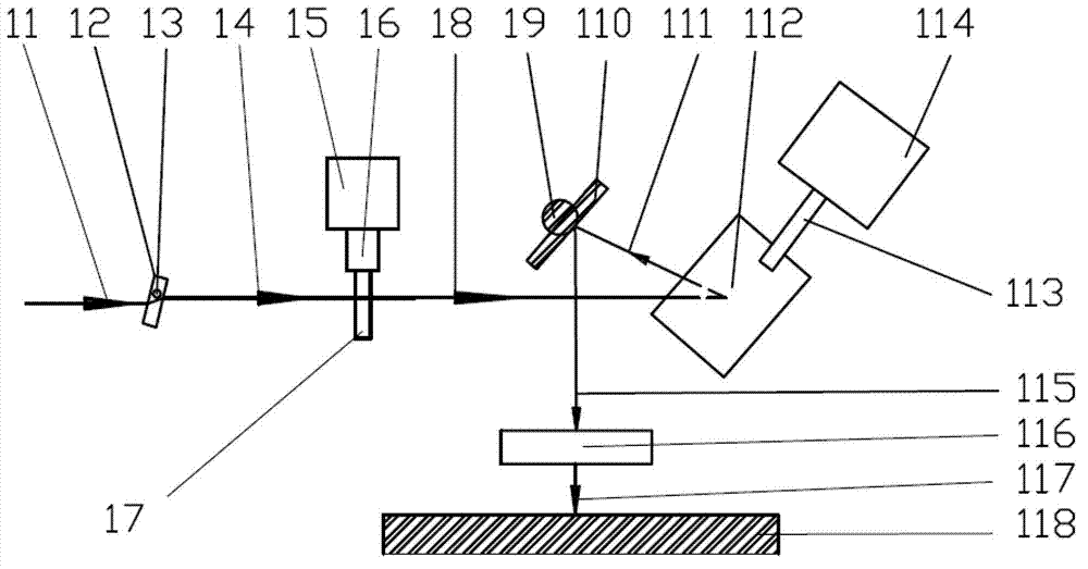
[0041] figure 1 It is a schematic diagram of the structure of the device for laser drilling of stainless steel sheets. The device includes a beam spatial modulation module and a galvanometer scanning flat-field focusing module. Wherein the beam spatial modulation module includes a first quartz plate glass 12 and a second quartz plate glass 17, the first quartz plate glass 12 is installed on the motor spindle 13 of the first motor (not shown in the figure), the second A quartz plate glass 17 is mounted on the motor spindle 16 of the second motor 15 . The first quartz plate glass 12 and the second quartz plate glass 17 can swing around the motor spindle. The galvanometer scanning flat-field focusing module includes a scanning galvanometer and a scanning flat-field focusing mirror. The scanning flat-field focusing mirror is a telecentric focusing mirror 116, and the scanning vibrating mirror includes a first reflecting mirror 112 and a second reflecting mirror 110, and the firs...

Embodiment 2

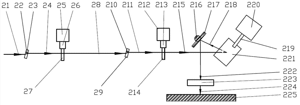
[0054] figure 2 Schematic diagram of the device structure for ceramic laser drilling, by figure 2 It can be seen that, on the basis of Embodiment 1, this embodiment adds two flat optical elements and two motors for controlling the oscillation of the flat optical elements. The device includes a beam spatial modulation module and a galvanometer scanning flat-field focusing module. Wherein the beam spatial modulation module comprises a first quartz plate glass 22, a second quartz plate glass 27, a third quartz plate glass 29 and a fourth quartz plate glass 214, and the first quartz plate glass 22 is installed on the first swing axis 23 , can swing around the first swing shaft 23, and the first swing shaft 23 is the motor main shaft of the first motor (not shown in the figure). The second quartz plate glass 27 is installed on the second swing shaft 26 and can swing around the second swing shaft 26 , and the second swing shaft 26 is the motor main shaft of the second motor 25 ....


PUM

PropertyMeasurementUnit
poweraaaaaaaaaa
diameteraaaaaaaaaa
wavelengthaaaaaaaaaa

Abstract

The invention relates to a large-size high-speed micropore drilling system which comprises a light beam space modulation module and a galvanometer scanning flat field focusing module. Particularly, the light beam space modulation module, particularly a plurality of transparent flat optical elements are combined with the galvanometer scanning flat field focusing module, the light beam space modulation module is used for modulating the space trace of a laser light beam, the galvanometer scanning flat field focusing module is used for focusing laser and rapidly switching laser spots at different machining positions, and the two modules are in division and cooperation. By the aid of the scheme, large-size micropore drilling can be realized, laser drilling efficiency and drilling quality are greatly improved, the large-size high-speed micropore drilling system is quite suitable for drilling straight holes, laser light beam filling and scanning shapes and sizes can be dynamically controlled, micropore drilling pore diameters can be dynamically changed, and fine structures can be flexibly machined.

Description

technical field [0001] The invention relates to the field of laser processing, in particular to a large-format micro-hole high-speed drilling system device. Background technique [0002] In the field of laser drilling, the laser focus is switched between holes, and galvanometer scanning is undoubtedly the fastest switching method, which is manifested in high acceleration and deceleration and displacement linear speed, as well as positioning speed. The two-dimensional displacement platform is undoubtedly a very slow method, and it is rarely used in general. [0003] The patent application number is 201010183539.7. The beam rotation module used cannot dynamically change the beam rotation diameter during processing, and is only suitable for the situation where the diameter of the drilling hole on the same workpiece surface changes little. So there are certain limitations. [0004] The application number is 200380110303.9. There is no problem with the galvanometer used to swit...

Claims


Application Information

Patent Timeline
Patent Type & Authority Applications(China)
IPC IPC(8): B23K26/38B23K26/04B23K26/046B23K26/382
Inventor 张立国
Owner 张立国
Why Eureka
Try Eureka