
Planar stereo lithography apparatus and method

A molding device and planar light technology, applied in the field of planar light-curing rapid prototyping devices, can solve the problems of parts production cost, investment cost, expensive system operation and maintenance costs, reduction of warping and deformation of molding materials, and unstable performance of molding materials, etc., to achieve Simplify equipment structure and process, solve warping deformation, and improve surface non-stick performance

Active Publication Date: 2013-07-17
SHAANXI HENGTONG INTELLIGENT MACHINE
View PDF4 Cites 23 Cited by
  • Summary
  • Abstract
  • Description
  • Claims
  • Application Information

AI Technical Summary

Problems solved by technology

[0002] In the existing photocuring rapid prototyping, the light spot formed by the ultraviolet laser is used to scan the horizontal plane (X direction and Y direction) to solidify the resin liquid. System operation and maintenance costs are very expensive
At the same time, in the existing planar light-curing rapid prototyping, the light source is used to irradiate the resin liquid from top to bottom, the performance of the molding material is unstable, the warping deformation is serious, and the utilization rate of the resin liquid is also low
Changing the resin tank holding the resin liquid into a glass bottom plate, so that the light source irradiates the resin liquid from the bottom up, not only improves the utilization rate of the resin liquid, but also reduces the warping and deformation of the molding material. However, the next layer of molding When the molded resin material is adhered to the glass bottom plate, it is not easy to peel off, and there is still the problem of warping and deformation, which reduces the molding efficiency

Method used


Image

  • Planar stereo lithography apparatus and method
  • Planar stereo lithography apparatus and method
  • Planar stereo lithography apparatus and method

Examples


Embodiment

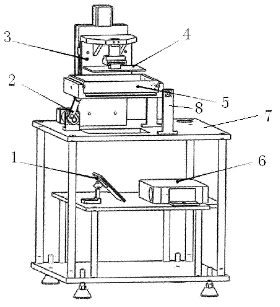
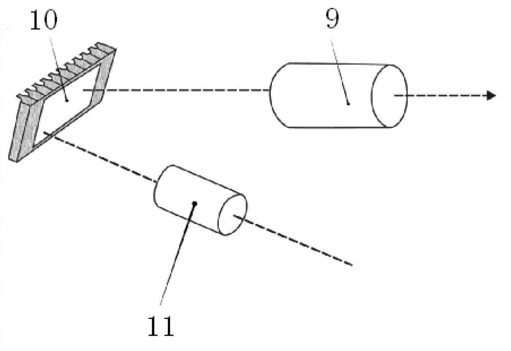
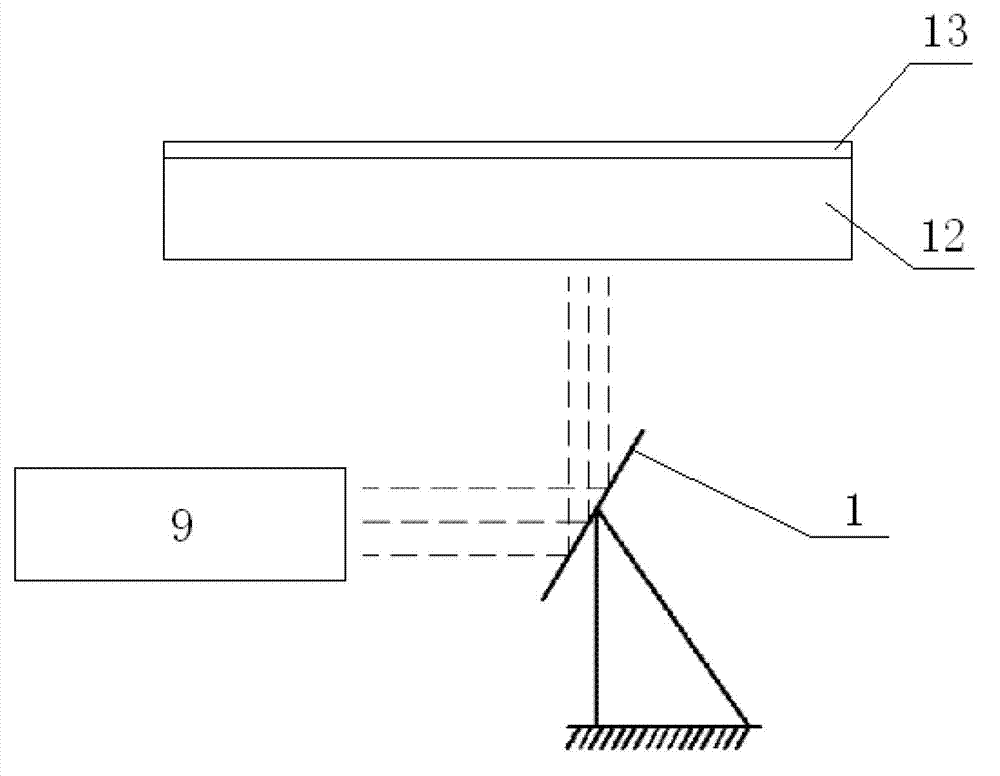
[0030] Digital projection surface curing rapid prototyping device, the device includes: a computer (external), which is equipped with layered data processing software, used to send cross-sectional graphics to the digital projector, and control the graphics projection mode of the projector; A modified digital projector equipped with an ultraviolet lamp head is used to receive image data from a computer, and project graphics onto the surface of the resin liquid according to the set exposure mode; a molding system, including a resin tank , above the resin tank, there is a working platform driven by the lifting system, and the formed entity is hung upside down on the working platform.

[0031] The digital projection technology is used to generate the layer profile of the solid part. Using the method of down-illumination and the shallower resin tank, the glass that can pass through ultraviolet light is used as the bottom plate of the resin tank. After one layer is cured, the light s...


PUM


Abstract

The invention provides a planar stereo lithography apparatus and method. The apparatus comprises an ultraviolet light digital projector, a resin storage tank and a workbench, wherein the bottom of the resin storage tank is prepared from glass which allows ultraviolet light to be transmitted, and a gap used for filling resin liquid is arranged between the lower end face of the workbench and the bottom of the resin storage tank. The resin liquid is injected into the gap located between the resin storage tank and the workbench; the contour of an ultraviolet light layer of an entity part generated by using a digital projection method forms an image on the resin liquid through a base plate of the resin storage tank so as to obtain a solidified layer with the contour of a corresponding layer; the workbench is lifted a layer higher, then the resin liquid is injected into a gap between the lower end face of the solidified layer and the resin storage tank, and exposure and solidification of a next layer are carried out. According to the invention, the problem of buckling deformation after stereo lithography is overcome, and the advantages of high molding precision, a fast molding speed, a simple process and low cost are obtained.

Description

technical field [0001] The invention belongs to the field of rapid prototyping, and in particular relates to a planar photocuring rapid prototyping device and method. Background technique [0002] In the existing photocuring rapid prototyping, the light spot formed by the ultraviolet laser is used to scan the horizontal plane (X direction and Y direction) to solidify the resin liquid. System operation and maintenance costs are very expensive. At the same time, in the existing planar photocuring rapid prototyping, the light source is used to irradiate the resin liquid from top to bottom, the performance of the molding material is unstable, the warping deformation is serious, and the utilization rate of the resin liquid is also low. Changing the resin tank holding the resin liquid into a glass bottom plate, so that the light source irradiates the resin liquid from the bottom up, not only improves the utilization rate of the resin liquid, but also reduces the warping and defor...

Claims


Application Information

Patent Timeline
IPC IPC(8): B29C67/00
Inventor 乐光王战勤同治强王立军程永丽王永信
Owner SHAANXI HENGTONG INTELLIGENT MACHINE
Learn More