Magnet unit, magnet array, magnetic levitation planar motor and lithographic device using magnetic levitation planar motor

A technology of magnet unit and plane motor, which is applied in electromechanical devices, photolithography process exposure devices, microlithography exposure equipment, etc., to achieve the effects of small magnetic leakage, light weight and strong magnetic density

Active Publication Date: 2013-07-17
SHANGHAI MICRO ELECTRONICS EQUIP (GRP) CO LTD
View PDF8 Cites 20 Cited by
  • Summary
  • Abstract
  • Description
  • Claims
  • Application Information

AI Technical Summary

Problems solved by technology

However, the discrete nature of the topological structure of the magnet array cannot avoid the large thrust ripple generated by the magnetic leakage and high-order harmonics of the magnetic array.

Method used


Image

  • Magnet unit, magnet array, magnetic levitation planar motor and lithographic device using magnetic levitation planar motor
  • Magnet unit, magnet array, magnetic levitation planar motor and lithographic device using magnetic levitation planar motor
  • Magnet unit, magnet array, magnetic levitation planar motor and lithographic device using magnetic levitation planar motor

Examples


Embodiment 1

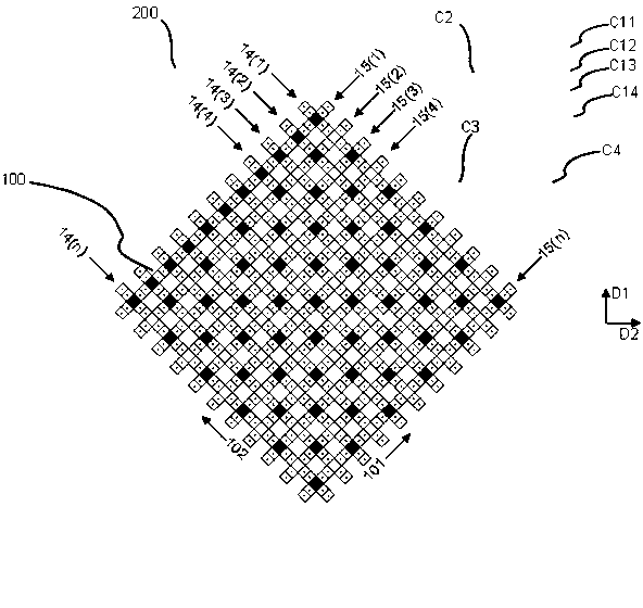
[0091] like figure 1 as shown, figure 1 It is a structural schematic diagram of a method for arranging a permanent magnet array of a planar motor provided by the present invention. The planar motor includes a permanent magnet array (or magnet array) 100 and a coil array 200 , and the coil array 200 is above or below the magnet array 100 and has a certain gap with the magnet array 100 . The magnetic levitation planar motor includes: a magnet array 100 and a coil array 200 . The magnet array 100 can move relative to the coil array 200 in a large range along the first direction 101 and the second direction 102 . Wherein, the magnet array 100 has a periodic sequence of rows 14 (n) and a periodic sequence of columns 15 (n), wherein n is a natural number. The row sequence 14(n) and the column sequence 15(n) of the magnet array 100 are arranged in the first direction 101 and the second direction 102 respectively. The distribution of magnet arrays in two directions is detailed as ...

Embodiment 2

[0101] Figure 10 gives figure 1 The second embodiment of the magnet array. like Figure 10 As shown, the second embodiment is a cross-sectional view of the periodic magnet array of the Halbach magnet group along the first axis direction 101 or the second direction 102 . This array comprises three types of magnets, wherein, the first prism magnet 136 of the third type magnet is vertically directed to the second prism magnet 137 of the third type magnet along the inclined plane magnetization direction, and the magnetic poles of the second prism magnet 137 of the third type magnet are The direction is parallel to the first axial direction 101 and points to the first type of N-pole square magnet 134, the third prismatic magnet 138 of the third type of magnet is vertically away from the second prismatic magnet 107 of the third type of magnet along the direction of magnetization on the slope, and the second prismatic magnet 107 of the third type of magnet. The magnetization dire...

Embodiment 3

[0104] Figure 13 gives figure 1 In the third embodiment of the magnet array, such as Figure 13As shown, the third embodiment is a cross-sectional view of the periodic magnet array of the Halbach magnet group along the first direction 101 or the second direction 102 . The array includes three types of magnets, wherein the first magnet 335 of the third type of magnet is parallel to the first axis direction 101 and points to the first type of N-pole trapezoidal prism magnet 337, and the magnetic pole direction of the second magnet 336 of the third type of magnet is It is parallel to the first axis direction 101 and points to the first type N-pole trapezoidal prism magnet 337 . The first type of trapezoidal prism magnets 337 a , 337 b have magnetization directions parallel to the axis 103 upward, and the second type of trapezoidal prism magnets 338 a , 338 b have magnetization directions parallel to the axis 103 downward. like Figure 13 As shown, the first type magnet, the ...


PUM


Abstract

The invention discloses a cross magnet unit which comprises a first magnet and a second magnet unit surrounding the first magnet. The first magnet is an N-pole magnet or an S-pole magnet. The magnetization direction of the first magnet is the Z-xis direction. The second magnet unit comprises four groups of magnet combinations with identical structure. The four groups of magnet combinations are respectively located in the X-axis direction and the Y-axis direction. The magnetization direction of the magnet combinations points at the N-pole magnet or is far away from the S-pole magnet. Each group of magnet combinations comprise at least two prism magnets, pyramid magnets or pyramid frustum magnets. A magnet array, a magnetic levitation planar motor and a lithographic device using the magnetic levitation planar motor are further disclosed.

Description

technical field [0001] The invention relates to the field of integrated circuit equipment manufacturing, in particular to a magnet unit, a magnet array, a magnetic levitation planar motor and a photolithographic device using the magnetic levitation planar motor. Background technique [0002] With the advancement of lithography technology and the rapid development of the semiconductor industry, there are four basic performance indicators for lithography equipment: line width uniformity (CD, Critical Dimension Uniformity), focal depth (Focus), overlay (Overlay) and productivity (Throughput). In order to improve the uniformity of line width, the workpiece table of lithography machine must improve the horizontal precision positioning ability; in order to improve the accuracy of focal depth error, the workpiece table must improve the vertical precision positioning ability; Improve its internal modality to improve dynamic positioning features. In addition, lithography equipment ...

Claims


Application Information

Patent Timeline
Patent Type & Authority Applications(China)
IPC IPC(8): H02K1/06H02K33/18G03F7/20
Inventor 吴立伟黄威陈庆生方洁
Owner SHANGHAI MICRO ELECTRONICS EQUIP (GRP) CO LTD
Why Eureka
Try Eureka