Inner-supporting clamp of constant-velocity universal joint bell housing

A technology of constant velocity universal joints and internal support fixtures, which is applied in the direction of expanding the mandrel, etc., can solve the problem of low reliability of clamping bell-shaped shell machining accuracy, non-uniform bell-shaped shell machining and positioning reference, and secondary clamping accuracy Error and other problems, to reduce the risk of large processing jump, high work intensity, and reduce the effect of relative motion

Active Publication Date: 2013-07-24
ZHEJIANG ODM TRANSMISSION TECH
View PDF6 Cites 13 Cited by
  • Summary
  • Abstract
  • Description
  • Claims
  • Application Information

AI Technical Summary

Problems solved by technology

The above-mentioned existing constant velocity universal joint bell shell outer diameter rough and fine turning machining and cavity end face turning positioning scheme can meet the general processing and positioning requirements of the bell shell under certain conditions, but there are certain restrictive factors: 1. The jaw chuck locks the cavity of the bell-shaped shell for positioning. The end face of the bell-shaped shell is covered by the three-jaw chuck. One clamping cannot complete the processing of the outer diameter of the bell-shaped shell and the end face of the cavity at the same time. The secondary clamping is low in efficiency and labor-intensive, and there are precision errors in the secondary clamping; 2. The design allowable value of the runout error of the three-jaw chuck can no longer meet the current high-standard manufacturing requirements of constant velocity universal joints. The accuracy and reliability of the clamping bell-shaped shell processing is low; 3. The positioning reference of the bell-shaped shell processing is not uniform, and the manufacturing accuracy of the inner cavity depth, rod length and overall length is limited

Method used


Image

  • Inner-supporting clamp of constant-velocity universal joint bell housing
  • Inner-supporting clamp of constant-velocity universal joint bell housing
  • Inner-supporting clamp of constant-velocity universal joint bell housing

Examples


Embodiment Construction

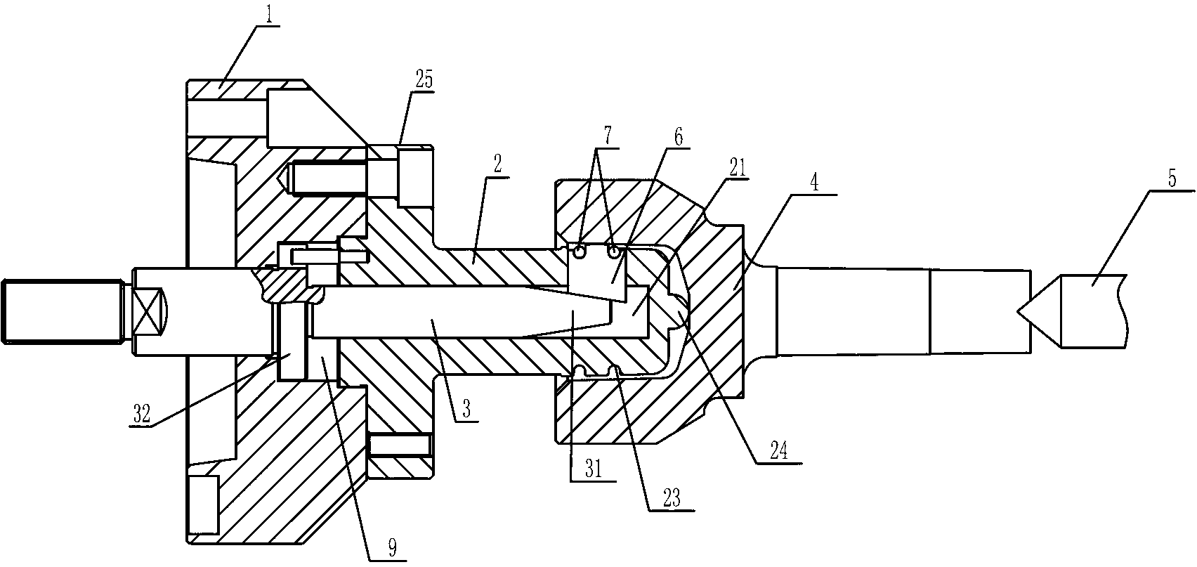
[0032] Such as Figures 1 to 5 As shown, a constant velocity universal joint bell-shaped shell internal support fixture includes a fixture main body 2, a top block 6 is provided on the front end side of the fixture main body 2, and a top block 6 is provided on the fixture main body 2. ejection structure. The end surface of the ejected end of the top block 6 is preferably a curved surface or a spherical surface.

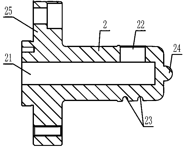
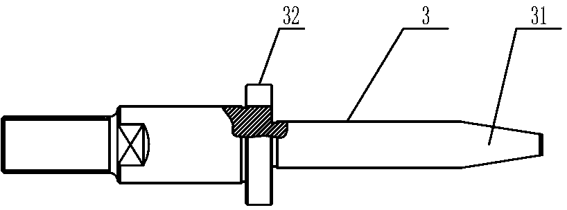
[0033] The fixture main body 2 is provided with a groove I21 with an opening located at the tail end of the fixture main body 2, and the side of the fixture main body 2 is provided with a through hole I22 passing through the inner wall of the groove I21 and the outer wall of the fixture main body 2, and the top block 6 is set in the through hole I22, and the ejection structure is a mandrel rod 3 extending from the mouth of the groove I21 into the groove I21 to push out the top block 6. The top block 6 and the core One end of the shaft pull rod 3 is an inclined surfa...


PUM


Abstract

The invention provides an inner-supporting clamp of a constant-velocity universal joint bell housing, which is mainly applied to the machining field of the constant-velocity universal joint bell housing. The inner-supporting clamp comprises a clamp body, wherein a top block is arranged on the side part at the front end of the clamp body; and an ejecting structure for ejecting the top block is arranged on the clamp body. The inner-supporting clamp of the constant-velocity universal joint bell housing can be used for clamping the constant-velocity universal joint bell housing by one step, and simultaneously completing rough-finish turning machining of the outer diameter and the end surface of the bell housing, so that secondary clamping error risks are removed and the time consumption for disassembling the clamped workpiece is reduced. Besides, the inner-supporting clamp of the constant-velocity universal joint bell housing has the advantages of being high in machining product precision, small in labor intensity and high in production efficiency.

Description

technical field [0001] The invention relates to the field of universal joint processing, in particular to a constant velocity universal joint bell-shaped shell internal support fixture. Background technique [0002] With the rapid development of the automobile industry, constant velocity universal joints occupy an important position in the automotive drive shaft industry with its unique constant angular velocity torque transmission and superior mechanical properties, and the quality of constant velocity universal joints is even more important. It is related to the performance and life of the product. The existing constant velocity universal joint manufacturing process has been greatly improved, but when processing the outer diameter of the bell shell, the technical scheme of locking the cavity of the bell shell with a conventional three-jaw chuck is mainly used to complete the bell shell. The outer diameter of the bell-shaped shell is rough and finely turned, so that it nee...

Claims


Application Information

Patent Timeline
Patent Type & Authority Applications(China)
IPC IPC(8): B23B31/40
Inventor 王立军林永庆范有生赵云黄风立
Owner ZHEJIANG ODM TRANSMISSION TECH
Why Eureka
Try Eureka