Quick correction method for galvanometer correction system

A correction system and correction method technology, applied in welding equipment, laser welding equipment, metal processing equipment, etc., can solve the problem of time-consuming, labor-intensive and cost-intensive galvanometer correction system, and achieve fast and convenient galvanometer correction, good technical effect, and time saving Effect

Inactive Publication Date: 2013-07-24
KUNSHAN THETA MICRO
View PDF10 Cites 19 Cited by
  • Summary
  • Abstract
  • Description
  • Claims
  • Application Information

AI Technical Summary

Problems solved by technology

[0007] The technical problem to be solved by the present invention is that the existing galvanometer calibration system is time-consuming, labor-intensive and costly. The present invention provides a fast calibration method for a precision galvanometer calibration system. The galvanometer calibration system is simple and stable, and the calibration method is fast and convenient.

Method used


Image

  • Quick correction method for galvanometer correction system
  • Quick correction method for galvanometer correction system
  • Quick correction method for galvanometer correction system

Examples


Embodiment 1

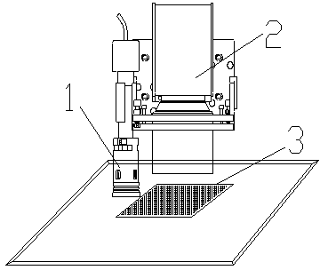
[0028] A galvanometer correction system, comprising a galvanometer correction plate, a galvanometer scanning module, a CCD image acquisition device, and an image processing module; the galvanometer scanning module controls the laser to form a matrix target on the galvanometer correction plate; the CCD image acquisition device Image acquisition is performed on the matrix target on the galvanometer correction board, and the image processing module processes the matrix target collected by the CCD image acquisition device, and then outputs a galvanometer compensation file to calibrate the galvanometer.

[0029] The quick correction method of described vibrating mirror correction system, comprises the following steps:

[0030] a) CCD correction, cut a circular hole with a diameter of 1mm on the galvanometer correction plate, move the CCD to the small circle position, move the machine so that the CCD captures the center of the circle, calculate the CCD Offset value, and input it to t...

Embodiment 2

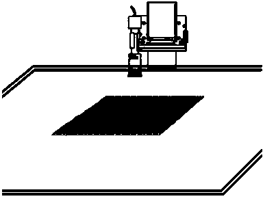
[0035] A vibrating mirror correction system, as attached figure 1 As shown, it includes: a galvanometer correction plate (clean and flat paper is enough), the laser is controlled by the galvanometer scanning module to form a matrix target on the galvanometer correction plate; a CCD image acquisition device is used to scan the galvanometer The matrix target on the correction board is used for image acquisition; the image processing module is used to process the matrix target collected by the CCD image acquisition device, and then output the galvanometer compensation file to calibrate the galvanometer.

[0036] The specific correction method is as follows:

[0037] 3. CCD correction: Cut a small circle (such as a circle with a radius of 0.5mm) on the galvanometer correction plate, move the CCD to the position of the small circle, move the machine so that the CCD captures the center of the circle, calculate the CCD Offset value and input it to the control System, so far, CCD cal...

Embodiment 3

[0042] A vibrating mirror correction system, as attached figure 1 As shown, it includes: a galvanometer correction plate (clean and flat paper is enough), the laser is controlled by the galvanometer scanning module to form a matrix target on the galvanometer correction plate; a CCD image acquisition device is used to scan the galvanometer The matrix target on the correction board is used for image acquisition; the image processing module is used to process the matrix target collected by the CCD image acquisition device, and then output the galvanometer compensation file to calibrate the galvanometer.

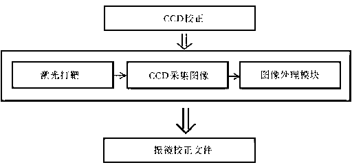
[0043] The method of galvanometer correction using the above galvanometer correction system is as follows: figure 2 As shown, the steps are as follows:

[0044] CCD correction: Cut a small circle (for example, a circle with a radius of 0.5mm) on the galvanometer correction plate, move the CCD to the position of the small circle, move the machine so that the CCD captures the ce...


PUM


Abstract

The invention relates to a quick correction method for a precise galvanometer correction system and mainly solves the problems that a galvanometer correction system in the prior art is time-consuming, labor-consuming and is high in cost. The invention adopts the quick correction method for the precise galvanometer correction system. The galvanometer correction system comprises a galvanometer correction plate, a CCD (charge coupled device) image acquisition device and an image processing module, wherein a galvanometer scanning module controls laser to form a matrix target on the galvanometer correction plate; the CCD image acquisition device is used for carrying out image acquisition to the matrix target on the galvanometer correction plate; and the image processing module is used for outputting a galvanometer compensation file to correct the galvanometer after processing the matrix target collected by the CCD image acquisition device. By adopting the technical scheme, the problems are well solved, and the quick correction method for the galvanometer correction system is applicable to laser machining industry.

Description

[0001] technical field [0002] The invention relates to a fast correction method of a precision vibrating mirror correction system. Background technique [0003] In laser processing technology, the galvanometer is generally used to control the optical path to process various complex graphics and characters; due to environmental temperature and humidity interference, motor loss of steps, etc., the galvanometer will produce deviations after a certain period of time, resulting in In the process of processing, deviations are formed in the splicing between the areas scanned by the galvanometer and the product processing fails. At this time, error compensation must be performed on the galvanometer to reduce this deviation. [0004] The traditional technology is to make a matrix target on the calibration board, and then combine with auxiliary measuring equipment (such as the second element, etc.) to measure, manually calculate the deviation between theory and reality, and then gen...

Claims


Application Information

Patent Timeline
Patent Type & Authority Applications(China)
IPC IPC(8): B23K26/42B23K26/70
Inventor 魏志凌宁军蔡猛
Owner KUNSHAN THETA MICRO
Why Eureka
Try Eureka