Clamping spring loading device of ball valve automatic assembling machine

A technology of automatic assembly machine and circlip, which is applied in the field of machinery, can solve the problems of product processing delay, difficulty in enterprise recruitment, low assembly efficiency, etc., and achieve the effect of high degree of automation, high degree of firmness, and high assembly efficiency

Active Publication Date: 2013-07-24
ZHEJIANG VALOGIN TECH
View PDF7 Cites 26 Cited by
  • Summary
  • Abstract
  • Description
  • Claims
  • Application Information

AI Technical Summary

Problems solved by technology

[0004] The existing way of manually assembling ball valves, even skilled workers, is faster at the beginning of assembly, but as time goes by, the assembly speed will decrease, the overall speed is slow, and the assembly efficiency is low
Moreover, in a large valve company, the output of ball valves is generally large in a year, so it is neces

Method used


Image

  • Clamping spring loading device of ball valve automatic assembling machine
  • Clamping spring loading device of ball valve automatic assembling machine
  • Clamping spring loading device of ball valve automatic assembling machine

Examples


Example Embodiment

[0030] Example one

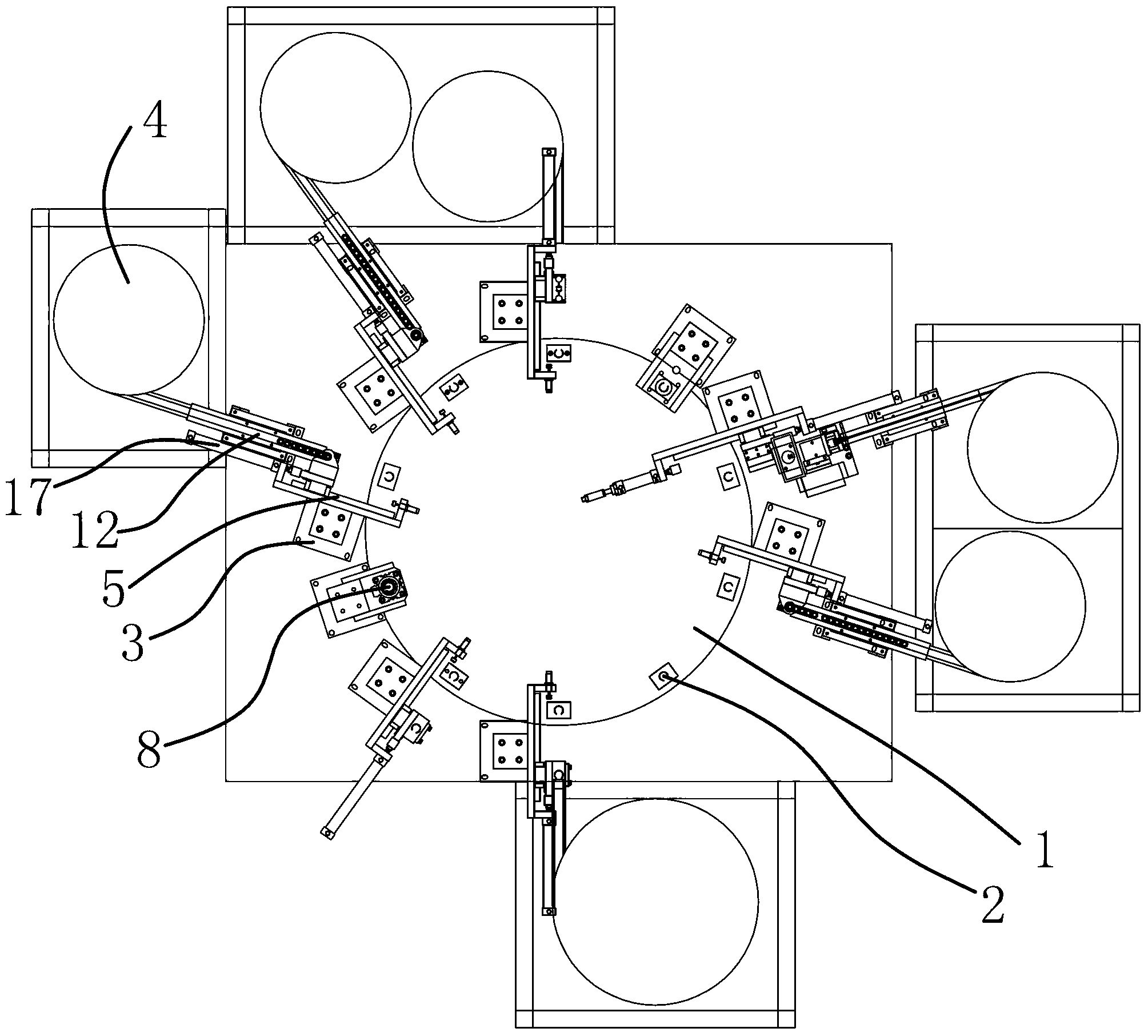
[0031] Such as figure 1 As shown, the circlip loading device is a part of an automatic ball valve assembly machine. The assembly machine includes a disk-shaped worktable 1 that can rotate around its axis. The worktable 1 is provided with ten molds at equal intervals along its circumferential direction. The base 2 and the mold base 2 are fixed on the worktable 1 by bolts. The mold base 2 has a fixing groove for fixing the valve body. The circlip loading device is located on the side of the worktable 1.

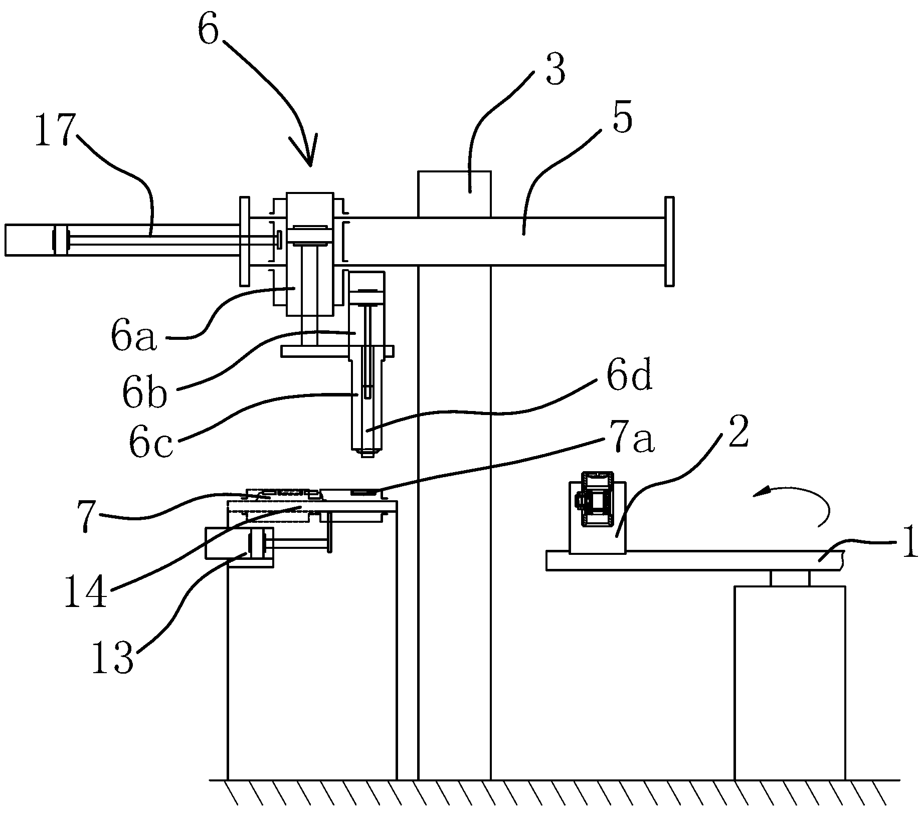
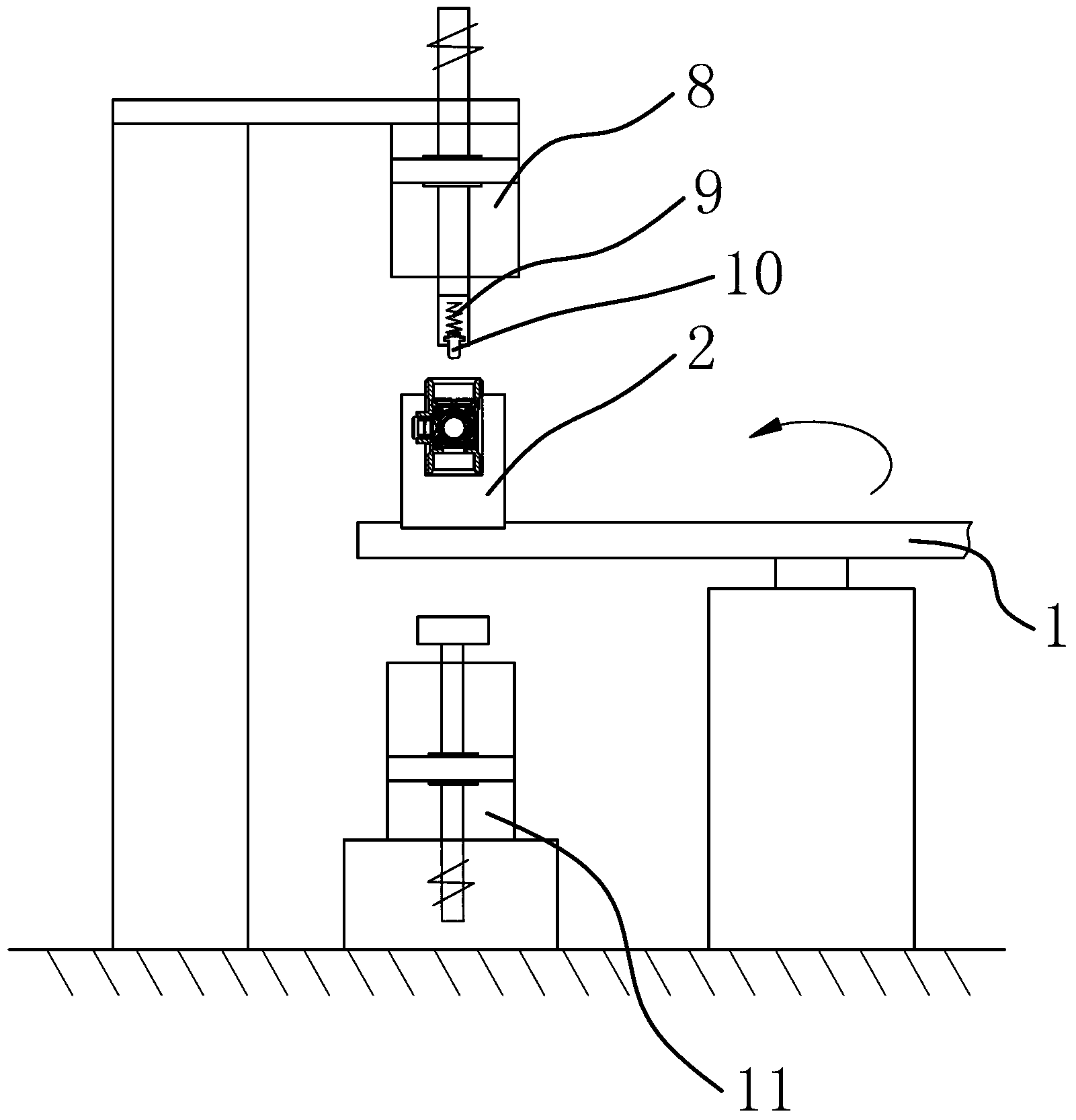
[0032] Such as figure 2 , image 3 As shown, the circlip loading device includes a bracket 3, a vibrating material tray 4, a driving mechanism, a manipulator 6, a slider 7, a compression cylinder 8, a spring 9, a punch 10, and a top plate cylinder 11.

[0033] The bracket 3 is located on the side of the workbench 1. The top of the bracket 3 is fixedly connected with a horizontal rail 5, and a manipulator 6 is movably connected to the horizontal rail 5. The manipu...

Example Embodiment

[0037] Example two

[0038] Such as Figure 4 As shown, the structure and principle of this embodiment and the first embodiment are basically the same. The difference is that in this embodiment, the driving mechanism includes a horizontal cylinder 15 and a slide rail 16, and the horizontal cylinder 15 and the slide rail 16 are both fixed on a fixed On the frame, the piston rod of the horizontal cylinder 15 is fixedly connected to the body 7b of the slider 7, and the slider 7 is installed in the sliding rail 16. The direction of the sliding rail 16 is the same as that of the horizontal cylinder 15 piston rod. The expansion and contraction of a 15-piston rod drives the sliding table 14 to move along the sliding rail 16.


PUM


Abstract

The invention provides a clamping spring loading device of a ball valve automatic assembling machine, belongs to the technical field of machinery, and aims to solve the problems that an existing ball valve is assembled manually, the assembling efficiency is low, and the labor cost is high and the like. According to the clamping spring loading device of the ball valve automatic assembling machine, the ball valve automatic assembling machine comprises an operating table which his fixedly connected with a mold seat, wherein the mold seat moves together with the operating table; and the clamping spring loading device is arranged at the side edge of the operating table, and comprises a rack, a vibration material disc and a driving mechanism, wherein the top of the rack is fixedly connected with a horizontal guide rail which is movably connected with a manipulator, a material outlet of the vibration material disc is provided with a slide block, the slide block is provided with a material receiving groove, the driving mechanism can drive the slide block to perform reciprocating motion between the material outlet of the vibration material disc and the manipulator, and the manipulator can convey a clamping spring in the material receiving groove into a valve body at the mold seat. The clamping spring loading device has the advantages of high automation degree, capability of improving the assembling efficiency of the ball valve and the like.

Description

technical field [0001] The invention belongs to the technical field of machinery and relates to an automatic ball valve assembly machine, in particular to a clamp spring loading device of the ball valve automatic assembly machine. Background technique [0002] With the rapid development of social economy, the competitiveness of labor-intensive valve enterprises is getting weaker and weaker. At present, there is a problem of difficult recruitment in the eastern coastal areas, which forces enterprises to develop in the direction of production automation and semi-automation to improve production efficiency. Reduce labor costs. [0003] Nowadays, valve companies generally assemble ball valves by hand when producing and assembling them. Taking a one-piece ball valve as an example, it includes a valve body, an O-ring, a valve stem, a valve ball, a circlip or a nut with an external thread, etc. When assembling, manually put the O-ring into the valve body, manually put the valve st...

Claims


Application Information

Patent Timeline
IPC IPC(8): B23P21/00B23Q7/18B23Q7/04
Inventor 戴美云张凤萍田保国李明吴金贵王纪秋文泉苏敏康舒平冬
Owner ZHEJIANG VALOGIN TECH
Why Eureka
Try Eureka